
Follow details and schedules
Follow details and schedules
Find the footing tag on the current plan and trace it to the matching detail and schedule. The plan establishes location. The detail explains the depicted arrangement and gives further references. The schedule supplies information for the identified footing type.
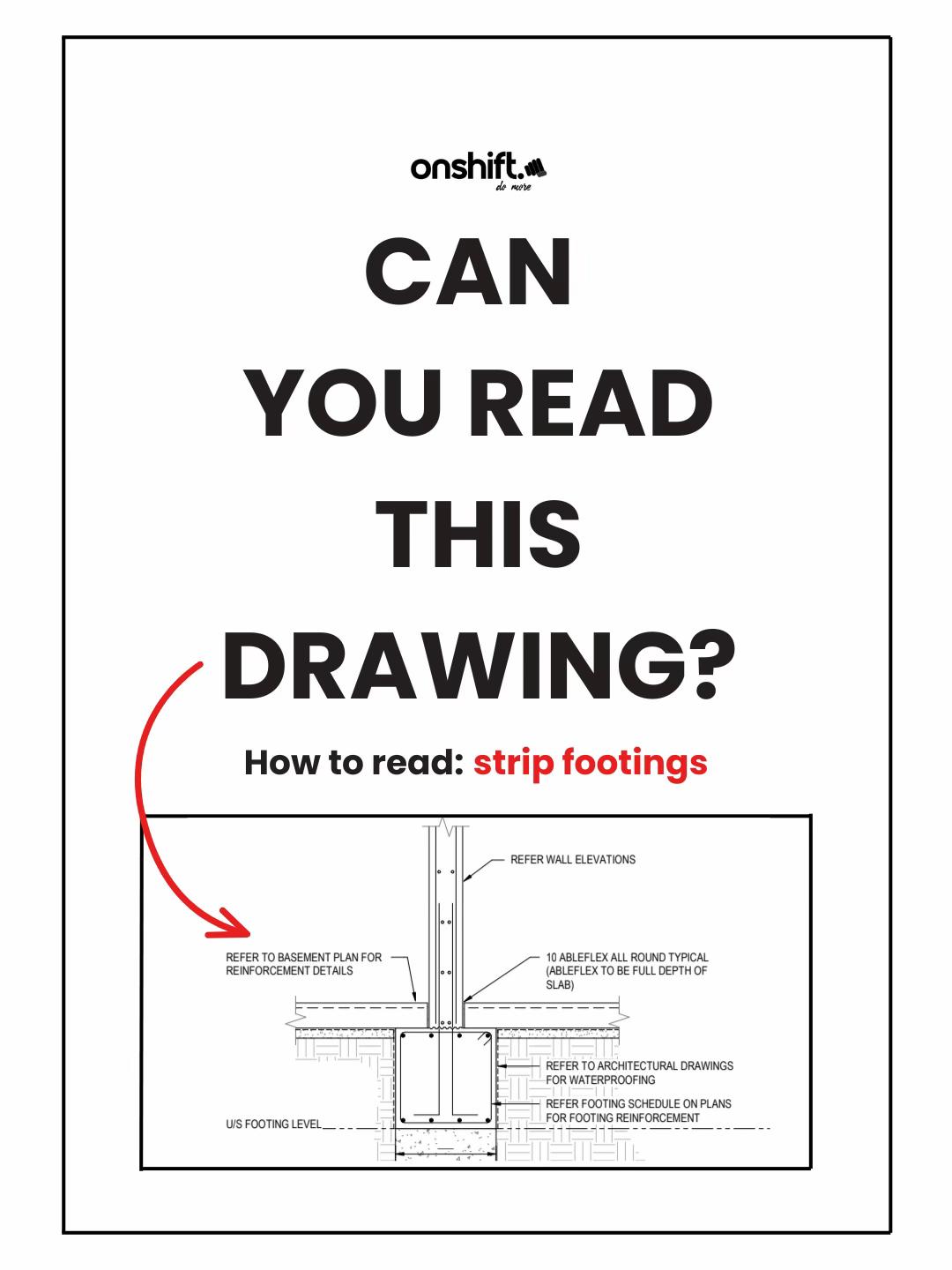
The Onshift image below is a section through a wall and footing. Its notes refer you to wall elevations, a basement plan for reinforcement information, architectural drawings for waterproofing and a footing schedule for footing reinforcement.
Those references are part of the information, not optional extras. This image alone does not specify a complete reinforcement requirement. Obtain the matching current documents, check the footing identifier and read the applicable notes before describing the requirements.
Worked example: The note 'REFER FOOTING SCHEDULE ON PLANS FOR FOOTING REINFORCEMENT' tells you where to look next. It does not tell you a bar size or spacing. Record that reference and locate the matching current schedule. If you do not have it, report the gap.
 Open full-size illustration
About this illustration and its limits
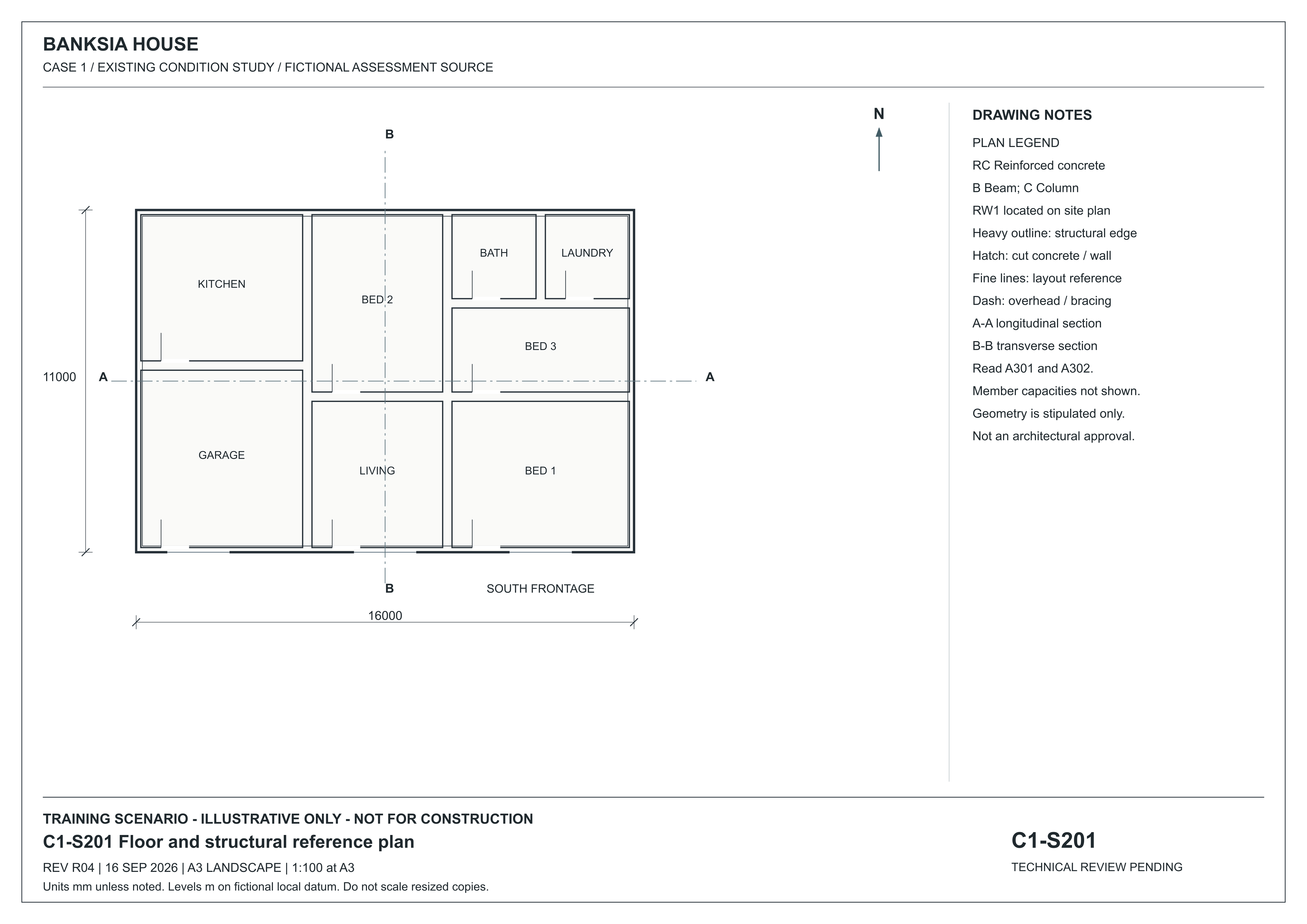
S201 shows the room arrangement and the written overall dimensions. Its A–A reference leads to A301 along the 16000 millimetre length; B–B leads to A302 across the 11000 millimetre width. It does not provide member capacities or connection design.
Existing-condition drawing for a fictional training project, R04, 16 September 2026. Not for construction. Use written dimensions; do not scale a resized screen image. Open the full-size drawing to read the title block and legend.
Source: Onshift · Banksia and Riverbend teaching drawings and initial records
 Open full-size illustration
About this illustration and its limits
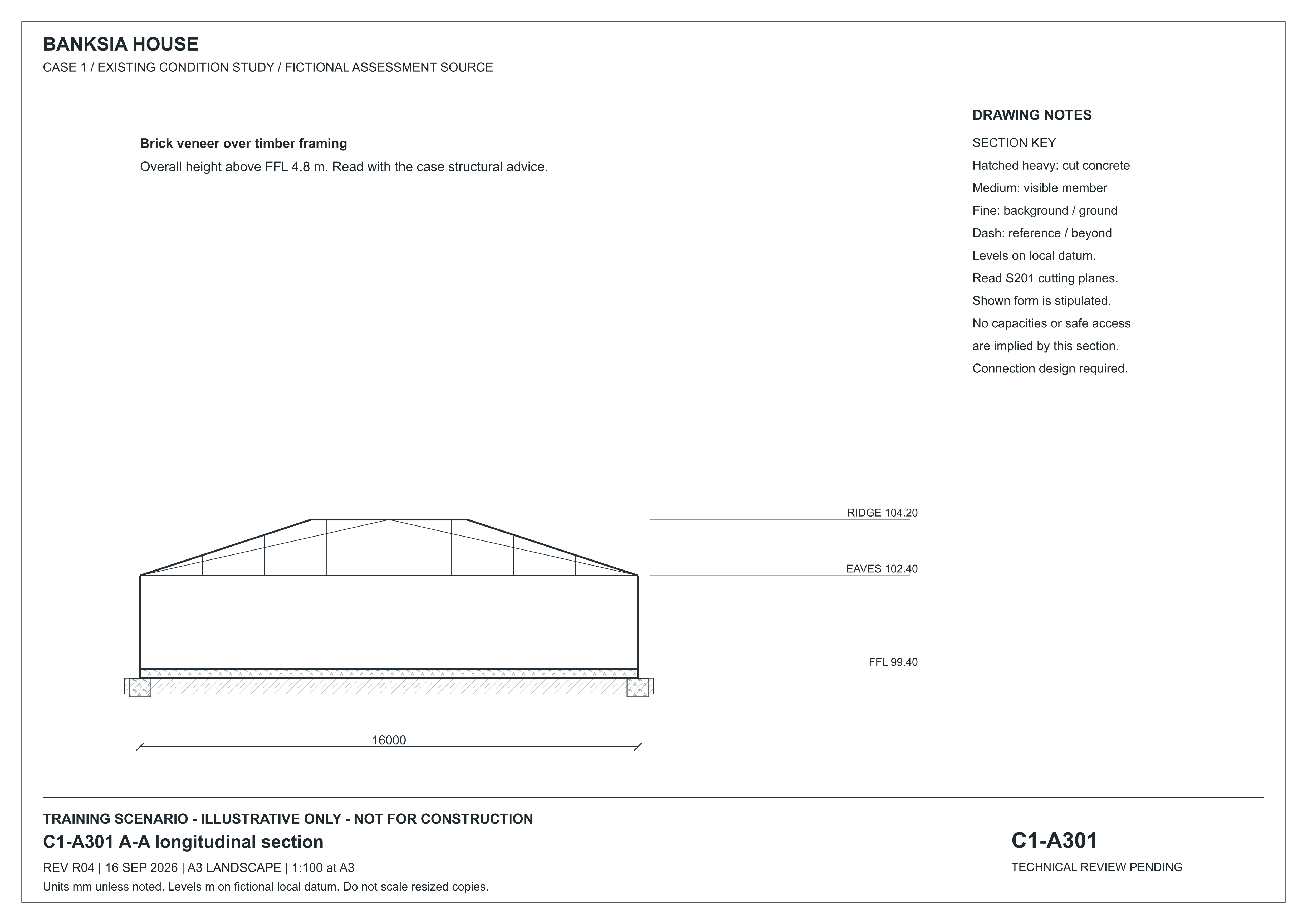
The ridge is 4.80 metres above finished floor: 104.20 minus 99.40. The levels are not Australian Height Datum. The section illustrates the construction system and cut materials; its notes require connection design before relying on connections.
Existing-condition drawing for a fictional training project, R04, 16 September 2026. Not for construction. Use written dimensions; do not scale a resized screen image. Open the full-size drawing to read the title block and legend.
Source: Onshift · Banksia and Riverbend teaching drawings and initial records
 Open full-size illustration
About this illustration and its limits
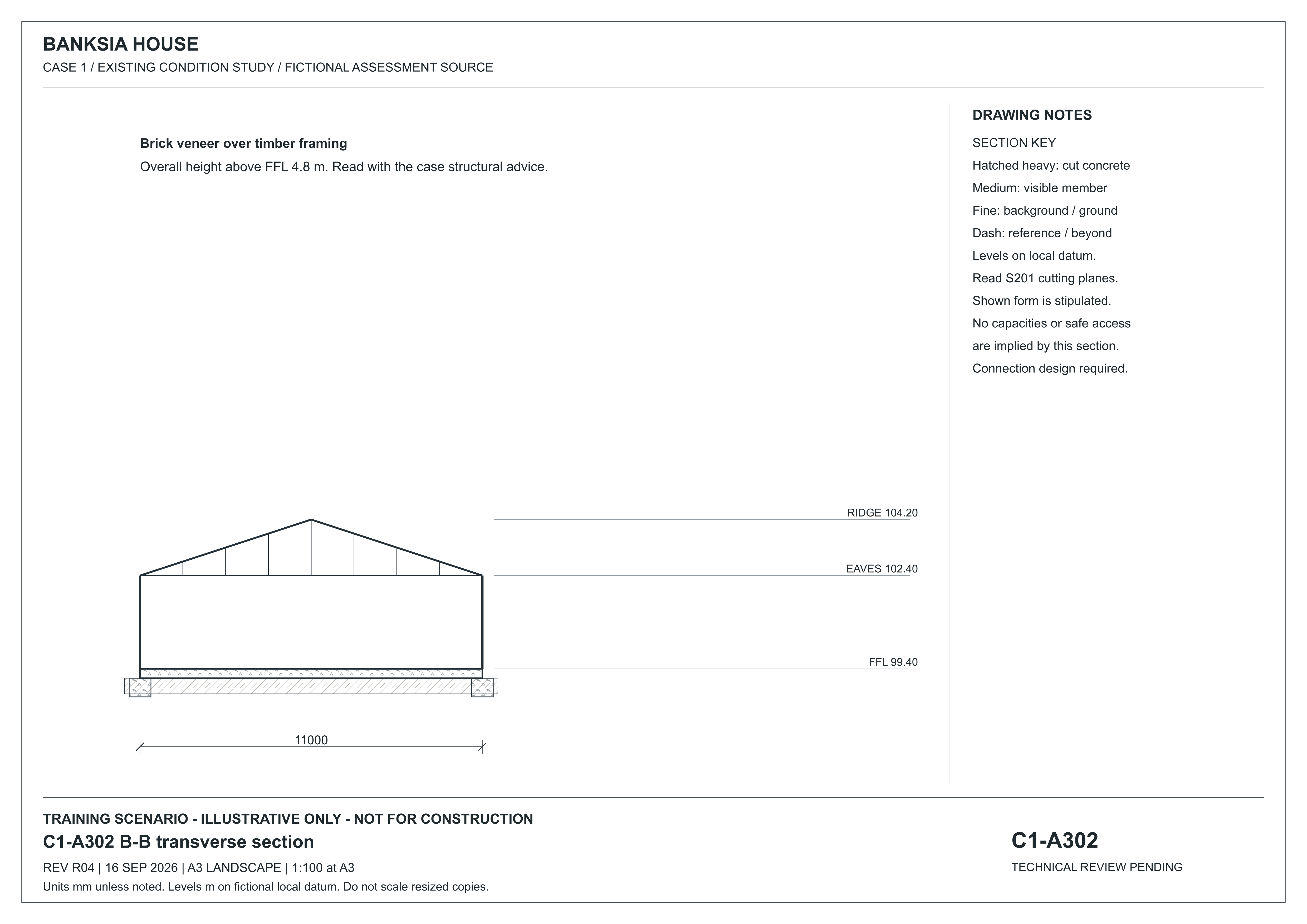
The transverse cut shares A301's vertical reference levels but has a different horizontal extent. Match the section letter, sheet identity and revision before combining readings.
Existing-condition drawing for a fictional training project, R04, 16 September 2026. Not for construction. Use written dimensions; do not scale a resized screen image. Open the full-size drawing to read the title block and legend.
Source: Onshift · Banksia and Riverbend teaching drawings and initial records
 Open full-size illustration
About this illustration and its limits
Read the wall and footing section, then follow its notes to the matching plans and footing schedule. The image does not supply final reinforcement sizes or spacing. Identify the missing references before describing what the footing requires.
Source: Onshift: Read strip-footing details
Follow the cut through the building
Coordinate a floor plan, two sections and their written dimensions.
Study the drawing
Locate a feature on the full sheet, then read its enlarged detail.
C1-S201 — revision R04 · 16 September 2026
Fictional existing-condition drawing. Not for construction. Dimensions are in millimetres unless noted; levels are in metres on a fictional local datum. Use written dimensions, not screen measurements.
The numbered markers point to features on the full sheet. Hover or focus a marker to locate it. Tap, click or press Enter to open its explanation and enlarged detail. The named buttons above do the same thing.
Choose a numbered marker or a named feature to locate it on the sheet.
Open original full-size C1-S201 R04
Read the sheet in text
S201 shows the room arrangement and the written overall dimensions. Its A–A reference leads to A301 along the 16000 millimetre length; B–B leads to A302 across the 11000 millimetre width. It does not provide member capacities or connection design.
Read a proposed building
SO01 adds a small proposed site office to the fictional BP-01 yard. Follow the same building through its plans, elevations, section and schedules.
Fictional teaching supplement · R01, 17 October 2026. Use the edition assigned by your assessor. BP-01 remains the assessed path project; these sources do not add a new practical task or authorise construction.
SO-A201 — Proposed floor plan and tags · A3 at 1:25
Use the floor plan for room arrangement, opening locations, dimensions and references to other sources.
The numbered markers point to features on the full sheet. Hover or focus a marker to locate it. Tap, click or press Enter to open its explanation and enlarged detail. The named buttons above do the same thing.
Choose a numbered marker or a named feature to locate it on the sheet.
Open SO-A201 with complete text equivalent · Open original full-size SO-A201
Reading limit: Door arcs and nominal openings do not establish a compliant clear passage or ordering size.
Door, window and finish schedules · Specification · Issue register
Download all four A3 drawings (PDF) · Study guide and worked examples
Narrated lesson
AI narration · transcript available. Pause to inspect the drawing when prompted. Your listening position is saved on this device; it is not assessment evidence.
Read the lesson transcript
A section is a cut through a building, taken at the line shown on another view. Open Banksia S two zero one when you are ready to study the drawings. Find the A to A cutting line, then open the A to A section, C one A three zero one. Check both identities and revisions. The written overall dimension is sixteen thousand millimetres. The section labels finished floor at ninety-nine point four zero and ridge at one hundred and four point two zero, on a fictional local datum. The difference is four point eight metres. Pause and make that comparison yourself. Then read the limitations. The section does not provide a connection design. The footing teaching image uses the same discipline: references lead you to schedules and other drawings. If those sources are absent, explain what remains unknown. A convincing picture is not a complete specification.
Worked example: Read strip-footing details
Follow the footing image's references to the other drawings and schedule. Explain which information you still need before describing the reinforcement requirements.
Optional example hosted on TikTok. You can also use the lesson explanation and drawings.
Find it in the source
Trace A-A and B-B on S201 to the titled sections A301 and A302. Compare the written 16000 mm and 11000 mm dimensions.
Try it yourself
Which section runs along the 16000 mm dimension? What is the ridge height above finished floor in A301, and can the section specify a connection design?
Practice only. Your notes clear when you change topics or leave this page. They are not saved or submitted as assessment evidence.
Follow details and schedules
Use the reading above, then apply it to the situation and task below.
Trace a footing requirement
Work within the authority and safety arrangements for your role.
A footing image refers to a footing schedule and other drawings that are not visible in the image.
Trace a footing requirement
Situation
A footing image refers to a footing schedule and other drawings that are not visible in the image.
Answer in your own words using the question and sources. This written explanation is separate from the project portfolio and observed practical task.
Image for this task
Use this Onshift teaching image to trace its references. It is an extract, so explain what additional documents you need; do not invent the missing engineering information.
Open the footing task image full sizeThe image alone does not establish final reinforcement sizes, spacing or construction approval.
Explain which references you must follow to establish the footing requirements, what information the image alone cannot establish and how you would report missing information. Do not nominate reinforcement sizes or spacing from this image.
Type your answer, or use your device's dictation to speak it into this box. Check the text before submitting.
Help with this answer (optional)
Trace the document chain and state the limits of this teaching example.
Check my answer (preview only — disabled). Show example layout
Synthetic example — layout demonstration only. Not AI output, not stored, not evidence.
What is clear
- Example layout only: the response identifies the project records being compared.
What to develop
- Example layout only: explain how you establish the authorised issue and report the inconsistency.
A question to think about
Which record would confirm the current authorised issue?
Read more in the Field Book
Teaching feedback only. It is not a mark or a result; your assessor decides the outcome.
Optional help and learning for this task
Read the matching fieldbook section
Task wording as issued
Explain which references you must follow to establish the footing requirements, what information the image alone cannot establish and how you would report missing information. Do not nominate reinforcement sizes or spacing from this image.
Preview only — disabled. A learner sends from the evidence page.
What to submit
Your own written explanation.