
Find the right drawing
Find the right drawing
Start with the question you need to answer. A site plan shows the building in relation to its site. A floor plan shows the horizontal arrangement of rooms, walls and openings. An elevation shows an outside face. A section shows a cut through the building.
A detail enlarges a particular junction or element. A specification describes project requirements in writing. These documents work together: a drawing may direct you to a detail, a schedule or a specification for the rest of the information.
Before reading the content, identify the project, drawing title, sheet number, revision and issue information. A useful-looking drawing from another project or an earlier issue is not a reliable starting point.
Worked example: You need to locate the proposed building in relation to a property boundary. Start with the current site plan, identify the boundary and building outline, then read the dimensions and related notes. The floor plan may help with the internal layout, but it is not your first source for the building's position on the site.
 Open full-size illustration
About this illustration and its limits
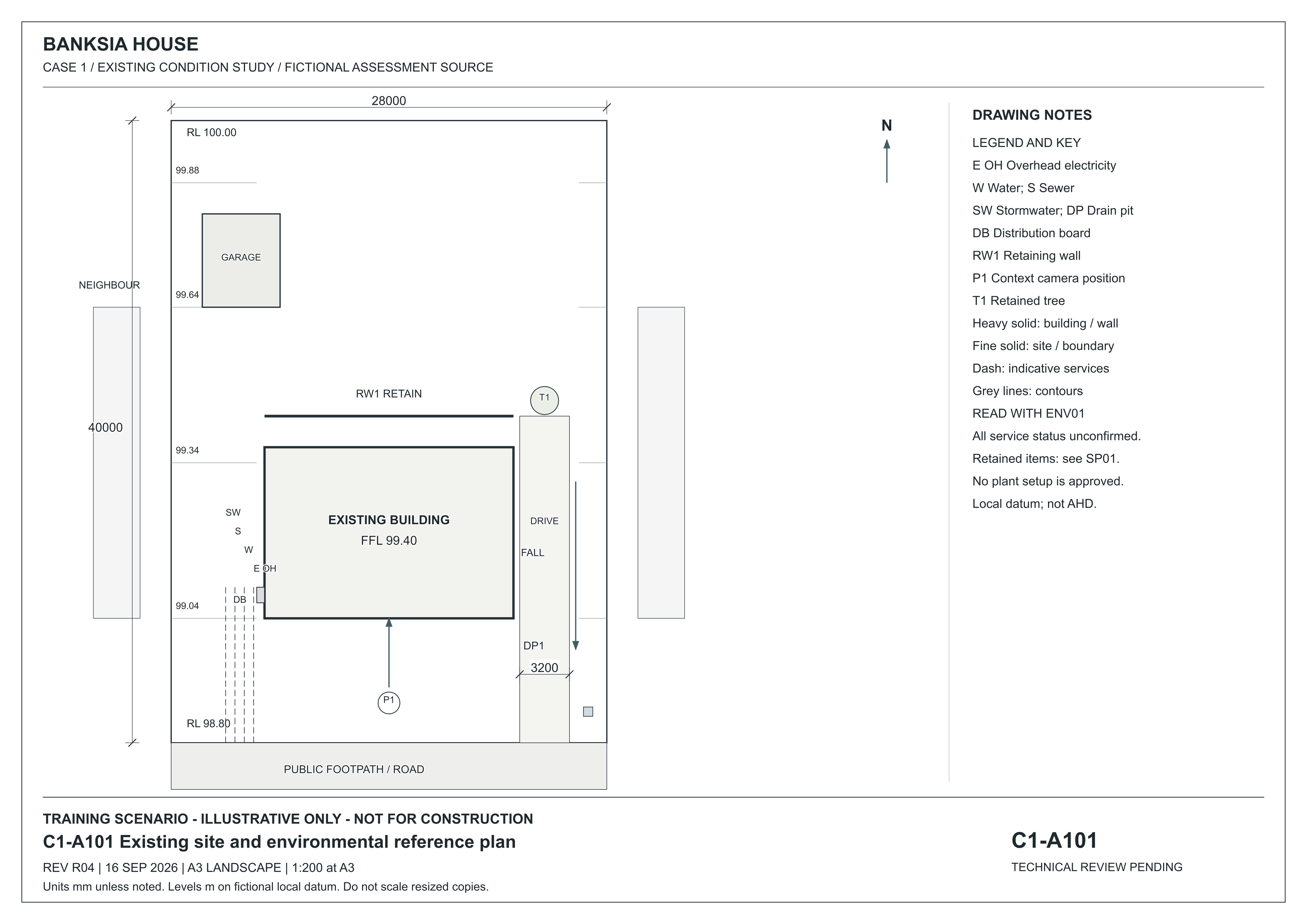
A101 places the main building and detached garage inside the lot. DP1 is a drain pit at the low southern frontage; T1 is the eastern retained tree and RW1 the rear garden wall. The legend identifies DB as distribution board and the service line abbreviations. Services are indicative and unconfirmed. Read ENV01 for environmental instructions and SP01 for project requirements.
Existing-condition drawing for a fictional training project, R04, 16 September 2026. Not for construction. Use written dimensions; do not scale a resized screen image. Open the full-size drawing to read the title block and legend.
Source: Onshift · Banksia and Riverbend teaching drawings and initial records
 Open full-size illustration
About this illustration and its limits
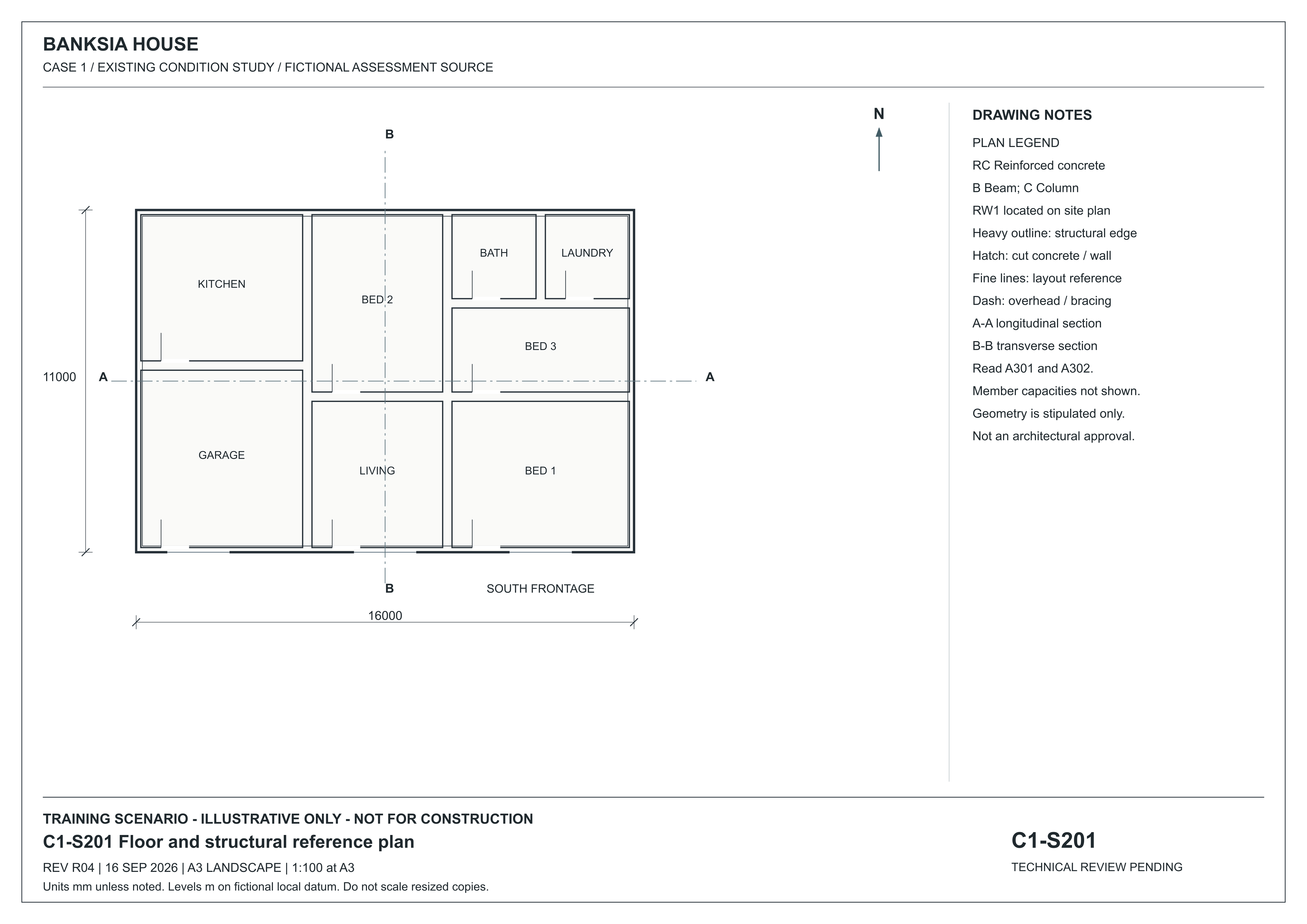
S201 shows the room arrangement and the written overall dimensions. Its A–A reference leads to A301 along the 16000 millimetre length; B–B leads to A302 across the 11000 millimetre width. It does not provide member capacities or connection design.
Existing-condition drawing for a fictional training project, R04, 16 September 2026. Not for construction. Use written dimensions; do not scale a resized screen image. Open the full-size drawing to read the title block and legend.
Source: Onshift · Banksia and Riverbend teaching drawings and initial records
 Open full-size illustration
About this illustration and its limits
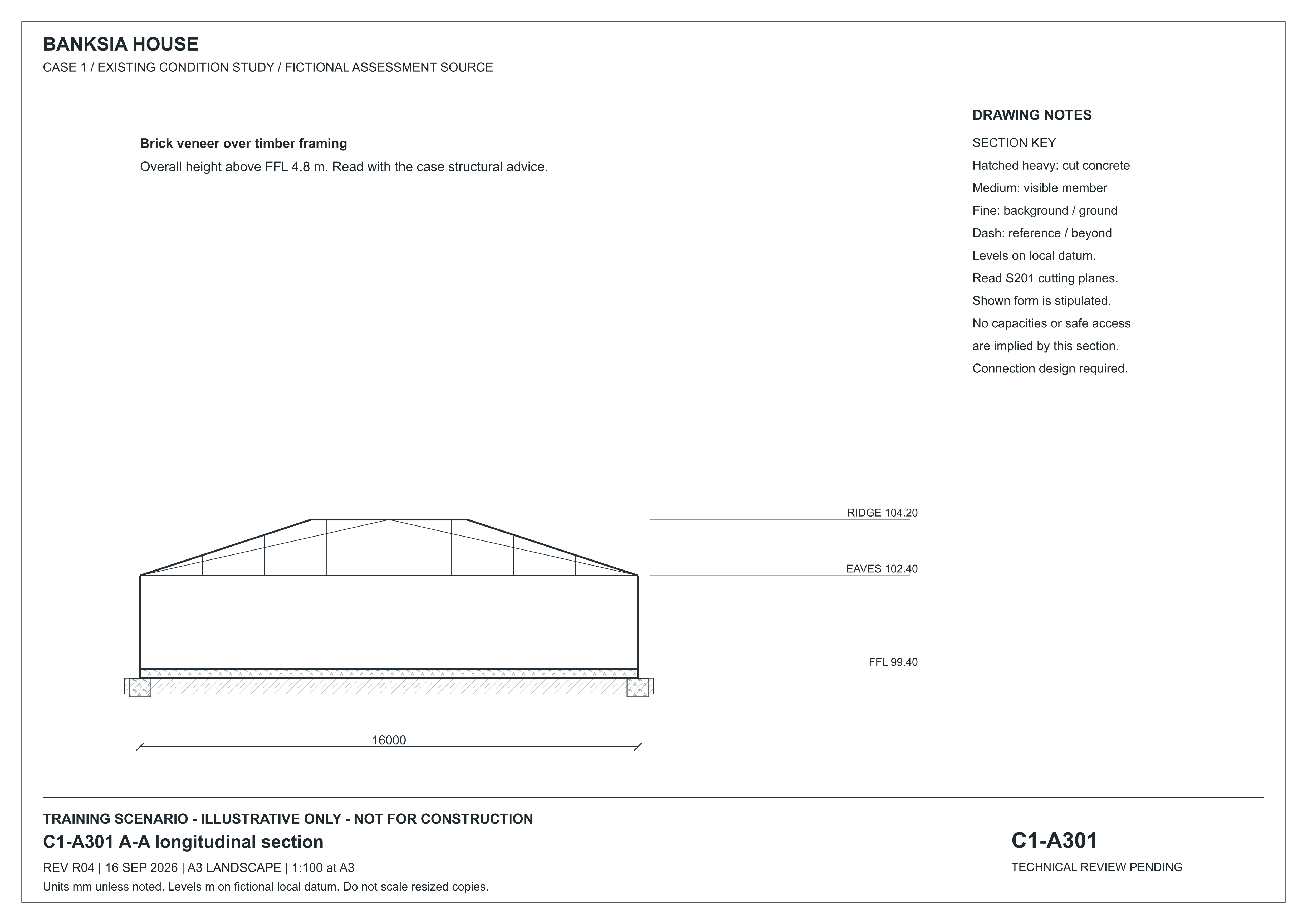
The ridge is 4.80 metres above finished floor: 104.20 minus 99.40. The levels are not Australian Height Datum. The section illustrates the construction system and cut materials; its notes require connection design before relying on connections.
Existing-condition drawing for a fictional training project, R04, 16 September 2026. Not for construction. Use written dimensions; do not scale a resized screen image. Open the full-size drawing to read the title block and legend.
Source: Onshift · Banksia and Riverbend teaching drawings and initial records
Choose the view that answers the question
Use the site plan, floor plan and section for different reading tasks.
Study the drawing
Locate a feature on the full sheet, then read its enlarged detail.
C1-A101 — revision R04 · 16 September 2026
Fictional existing-condition drawing. Not for construction. Dimensions are in millimetres unless noted; levels are in metres on a fictional local datum. Use written dimensions, not screen measurements.
The numbered markers point to features on the full sheet. Hover or focus a marker to locate it. Tap, click or press Enter to open its explanation and enlarged detail. The named buttons above do the same thing.
Choose a numbered marker or a named feature to locate it on the sheet.
Open original full-size C1-A101 R04
Read the sheet in text
A101 places the main building and detached garage inside the lot. DP1 is a drain pit at the low southern frontage; T1 is the eastern retained tree and RW1 the rear garden wall. The legend identifies DB as distribution board and the service line abbreviations. Services are indicative and unconfirmed. Read ENV01 for environmental instructions and SP01 for project requirements.
Read a proposed building
SO01 adds a small proposed site office to the fictional BP-01 yard. Follow the same building through its plans, elevations, section and schedules.
Fictional teaching supplement · R01, 17 October 2026. Use the edition assigned by your assessor. BP-01 remains the assessed path project; these sources do not add a new practical task or authorise construction.
SO-A201 — Proposed floor plan and tags · A3 at 1:25
Use the floor plan for room arrangement, opening locations, dimensions and references to other sources.
The numbered markers point to features on the full sheet. Hover or focus a marker to locate it. Tap, click or press Enter to open its explanation and enlarged detail. The named buttons above do the same thing.
Choose a numbered marker or a named feature to locate it on the sheet.
Open SO-A201 with complete text equivalent · Open original full-size SO-A201
Reading limit: Door arcs and nominal openings do not establish a compliant clear passage or ordering size.
Door, window and finish schedules · Specification · Issue register
Download all four A3 drawings (PDF) · Study guide and worked examples
Narrated lesson
AI narration · transcript available. Pause to inspect the drawing when prompted. Your listening position is saved on this device; it is not assessment evidence.
Read the lesson transcript
Start with the question, then choose the view. To locate the building on its lot, use a site plan. To understand the room arrangement, use a floor plan. To see a vertical relationship, follow a section. When you can view the drawings, compare Banksia sheets A one zero one, S two zero one and A three zero one. Keep the C one project prefix and revision R zero four together. The site plan shows the southern public frontage. The floor plan shows the living room. The longitudinal section shows floor, eaves and ridge levels. These views complement one another; they do not answer the same question. Now pause. Find the sheet you would use for each of those three questions, and explain your choice. Next, ask what the drawing leaves out. A material may be identified on a plan but specified in a written document. Reading the job means following that chain, not guessing from the picture.
Audio guide: Follow one building through the drawing set
AI narration with a matching transcript. Your listening position is saved on this device; listening is not assessment evidence.
Read the audio guide transcript
A drawing set describes the same project in several ways. Each view answers a different question. Our example is S O zero one, a fictional proposed site office in the B P zero one yard. Before comparing views, check the project, drawing number and revision in each title block. The drawing set is revision R zero one. Its issue register identifies the sources that belong together.
Start with the site plan, S O A one zero one. It locates the office against the boundaries and retained features. The office is five metres wide and three metres deep, beside the northern apron. This establishes a position in the teaching model. It does not prove an underground service clearance or permission to build.
Now use the floor plan, S O A two zero one. A floor plan looks down through the building. It shows two rooms, wall positions, openings and written dimensions. A door arc indicates the direction of its swing. The tag D zero one identifies the entrance door. Follow that tag to the opening schedule. It gives a nominal opening of one thousand millimetres wide by two thousand one hundred millimetres high. Nominal opening size is different from a verified clear passage or an ordering size.
An elevation shows an outside face. On S O A three zero one, the north elevation shows window W zero one. The schedule identifies fixed glazing and its opening size. Fixed glass does not establish that ventilation requirements have been met. A section shows a cut through the building instead. Follow the A to A reference on the floor plan to S O A four zero one. It cuts through the office and north window. The finished floor level is one hundred point three zero zero. The ceiling is one hundred and three point zero zero zero. Their difference is two point seven metres. These are levels on a fictional local datum.
Use schedules and the specification to complete the reading. The office floor tag F zero one leads to carpet tiles. The entry and store tag F zero two leads to sheet vinyl. Read the finish, material and reference together. A coloured surface alone cannot establish the specified product.
Finally, inspect the limits. The office floor is two hundred and eighty-five millimetres above the stipulated apron centreline. A suitable approach, landing and threshold have not been designed. Structural, service and approval information is also incomplete. Record those gaps rather than inventing a solution. When you can view the screen, trace one opening through its plan, elevation and schedule, then explain what each source adds.
Worked example: How to read drawing plans
Compare the drawing views, then use the site plan, floor plan and section to choose the view that answers your question.
Optional example hosted on TikTok. You can also use the lesson explanation and drawings.
Find it in the source
Compare A101's lot boundary with S201's room arrangement, then find the floor and ridge levels on A301.
Try it yourself
Which sheet would you use to find the public frontage, the living room and the ridge level? Why are they different views?
Practice only. Your notes clear when you change topics or leave this page. They are not saved or submitted as assessment evidence.
Find the right drawing
Use the reading above, then apply it to the situation and task below.
Choose and explain the drawing
Work within the authority and safety arrangements for your role.
A new worker needs to know which project information answers each question.
Choose and explain the drawing
Situation
A new worker needs to know which project information answers each question.
Answer in your own words using the question and sources. This written explanation is separate from the project portfolio and observed practical task.
Explain the features and purpose of a construction plan, site plan, cross-section, engineering plan and project specification. Explain how dimensions, notes, illustrations and structural details help you read the set. Give a suitable construction question for each document type.
Type your answer, or use your device's dictation to speak it into this box. Check the text before submitting.
Help with this answer (optional)
Explain the purpose, the information it supplies and a question it answers. Include how the drawings and specification work together.
Check my answer (preview only — disabled). Show example layout
Synthetic example — layout demonstration only. Not AI output, not stored, not evidence.
What is clear
- Example layout only: the response identifies the project records being compared.
What to develop
- Example layout only: explain how you establish the authorised issue and report the inconsistency.
A question to think about
Which record would confirm the current authorised issue?
Read more in the Field Book
Teaching feedback only. It is not a mark or a result; your assessor decides the outcome.
Optional help and learning for this task
Read the matching fieldbook section
Task wording as issued
Explain the features and purpose of a construction plan, site plan, cross-section, engineering plan and project specification. Explain how dimensions, notes, illustrations and structural details help you read the set. Give a suitable construction question for each document type.
Preview only — disabled. A learner sends from the evidence page.
What to submit
Your own written explanation.