Open full-size vector drawing · Use written dimensions; do not scale the screen.
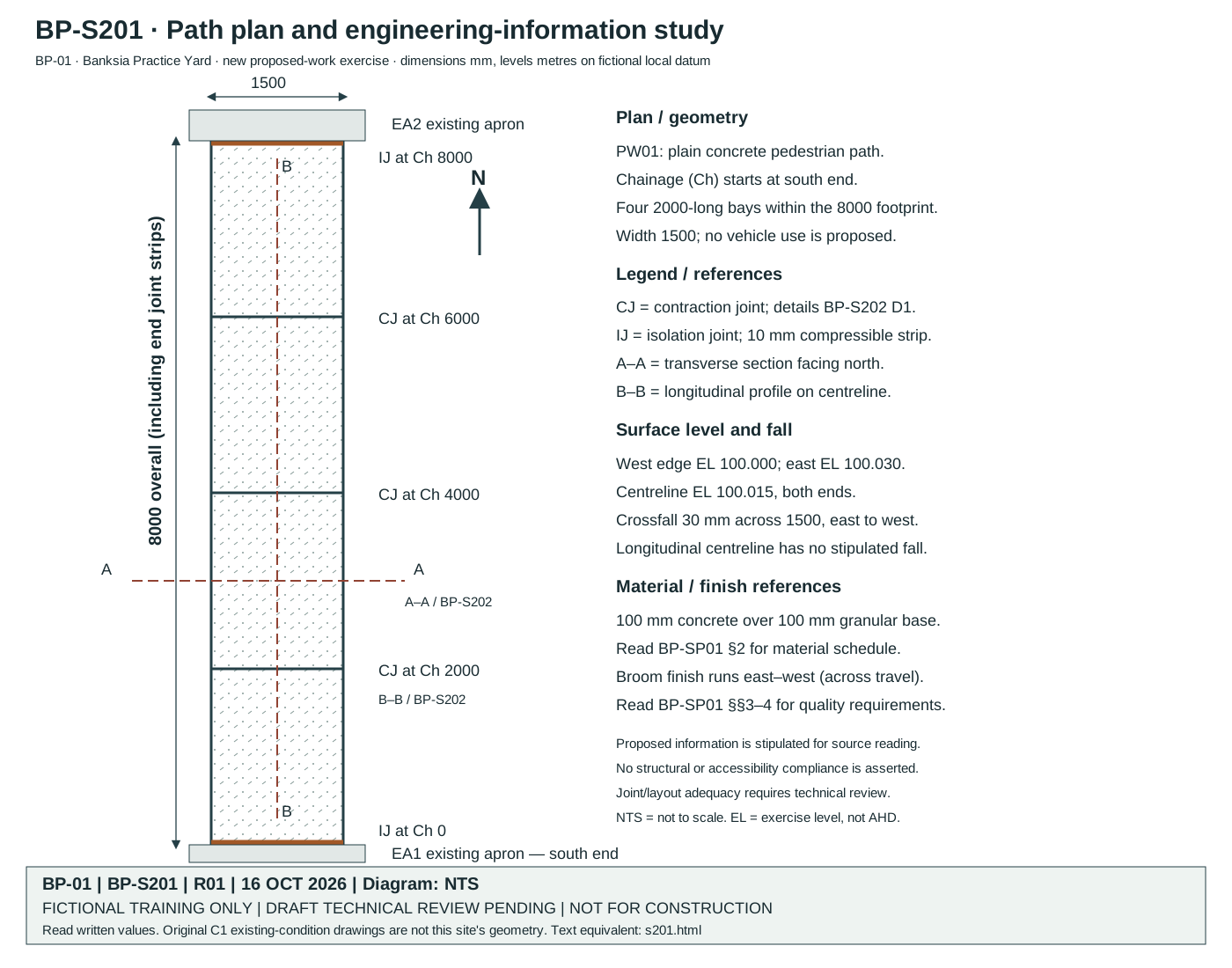
PW01 geometry and construction
Proposed work: a plain concrete pedestrian path on a compacted granular base, between existing exercise aprons EA1 and EA2. No vehicle use is proposed. Overall footprint is 8000 mm long × 1500 mm wide, including the end isolation-joint strips. Refer to BP-A101 for its coordinates and setbacks. Ch (chainage) starts at the south end: Ch0 at N2000, Ch8000 at N10000.
| Information | Stipulated requirement |
|---|---|
| Layer reference | Nominal 100 mm concrete over nominal 100 mm compacted granular base; BP-S202 D1 and BP-SP01 §2. |
| CJ — contraction joints | At Ch2000, Ch4000 and Ch6000. The plan divides the overall footprint into four 2000 mm bays; end strips are included in that overall footprint. |
| IJ — isolation joints | 10 mm compressible strip at each apron interface, Ch0 and Ch8000. |
| A–A / BP-S202 | Transverse section facing north, at Ch3000. |
| B–B / BP-S202 | Longitudinal centreline profile from Ch0 to Ch8000. |
| West edge / east edge levels | EL100.000 west and EL100.030 east throughout the path. |
| Centreline level | EL100.015 at both ends and throughout the centreline profile. |
| Surface fall | 30 mm across 1500 mm, from east to west. No longitudinal centreline fall is stipulated. |
| Finish | Broom texture east–west, across the north–south direction of travel; BP-SP01 §3. |
Drawing purpose and limits
This is a fictional construction/engineering-information study sheet: it provides proposed geometry, material-layer and joint references for interpretation. It has not been prepared or approved as an engineered design. Site suitability, adequacy of unreinforced concrete/joints, drainage and accessibility require technical review. Do not infer them from the illustration.