The PDF is A3 landscape (420 x 297 mm). Print at 100%, not fit-to-page, and check the scale bar. Screen size is not a measurement scale. On a phone, swipe the drawing or use the complete text equivalent below.
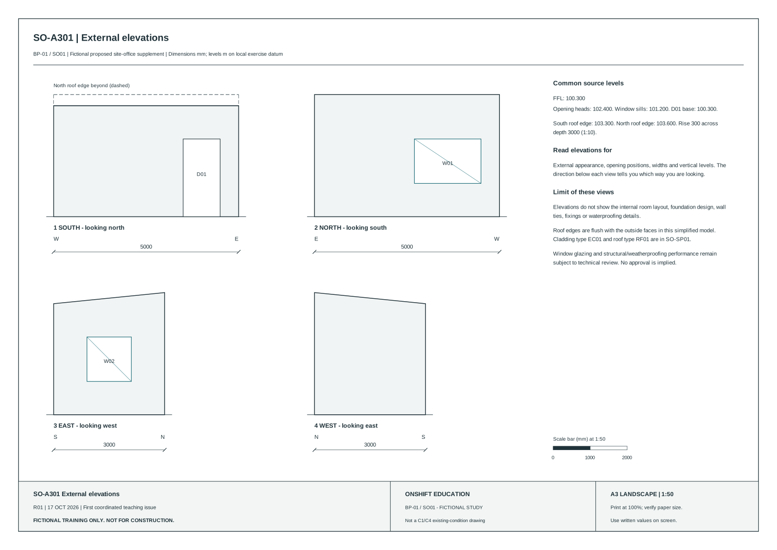
Read the view direction
| Elevation | Viewing direction / page ends | Openings |
|---|---|---|
| South | Looking north; west left, east right. Width 5000. | D01 on eastern side; nominal opening 1000 x 2100. High north roof edge is shown dashed beyond the low south edge. |
| North | Looking south; east left, west right. Width 5000. | W01 towards the west, therefore right-hand part of this elevation; 1800 x 1200. |
| East | Looking west; south left, north right. Width 3000. | W02 centred between local Y900 and Y2100; 1200 x 1200. Roof rises to the right. |
| West | Looking east; north left, south right. Width 3000. | No scheduled opening; roof falls to the right. |
Coordinated levels
| Reference | Level / relationship |
|---|---|
| FFL | 100.300. |
| Door D01 base / head | 100.300 / 102.400; height 2100. |
| Windows W01 and W02 sill / head | 101.200 / 102.400. Sill 900 above FFL, height 1200. |
| South / north roof edge | 103.300 / 103.600, respectively 3000 / 3300 above FFL. |
| Roof rise | 300 across building depth 3000: 1:10 in this model. |
Purpose and limitations
Elevations show external appearance, opening position and vertical relationships. They do not establish room layout, foundation design, connections, wall ties, glazing performance or compliance. Roof edges are flush with wall outside faces in this simplified exercise. EC01 wall cladding and RF01 sheet roof are described in SO-SP01. The fixed-glazing diagonal is only a local graphical glass identifier; operation is established by the schedule.