The PDF is A3 landscape (420 x 297 mm). Print at 100%, not fit-to-page, and check the scale bar. Screen size is not a measurement scale. On a phone, swipe the drawing or use the complete text equivalent below.
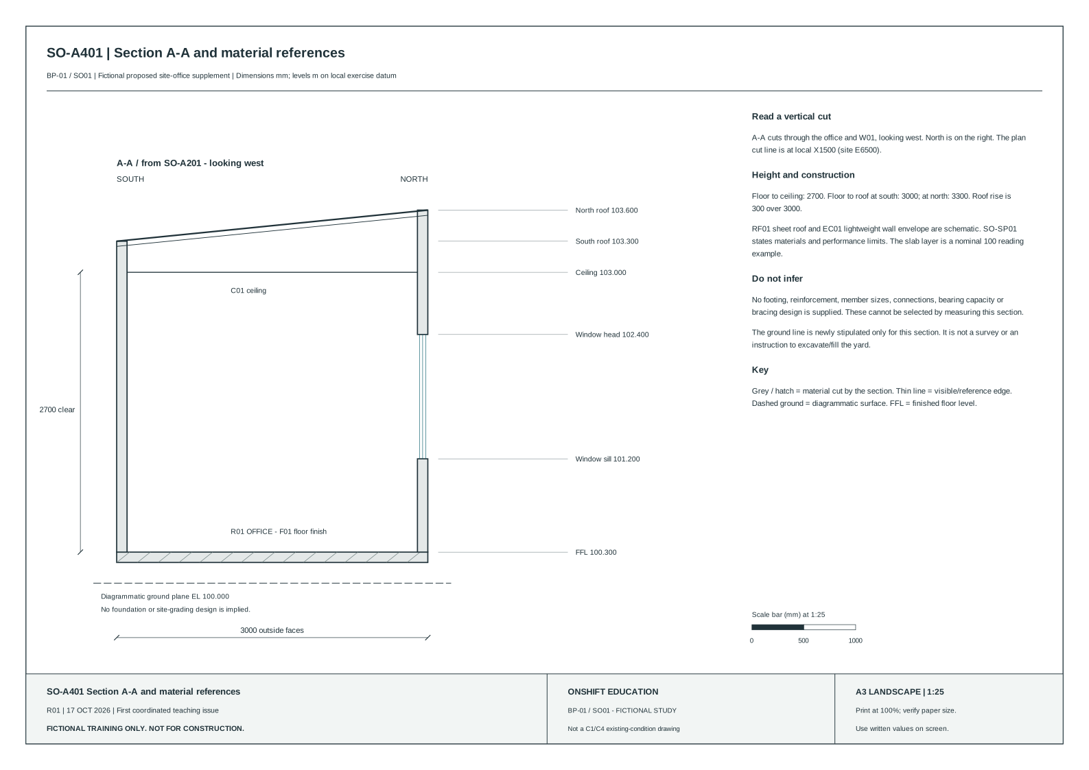
Section A-A and viewing direction
SO-A401 R01, A3 at 1:25. A-A comes from SO-A201, cutting north-south at site E6500 and looking west. South is left; north is right. It cuts the office and W01. The outside-face depth is 3000.
Vertical relationships
| Item | Level or dimension |
|---|---|
| Floor and ceiling | FFL100.300 to ceiling103.000 = 2700 clear height. |
| South roof edge | 103.300 = 3000 above finished floor. |
| North roof edge | 103.600 = 3300 above finished floor. |
| Roof rise | 300 across 3000; no roof-member design is given. |
| W01 sill and head | 101.200 and102.400, therefore 900 sill above floor and1200 opening height. |
| Slab illustration | 100 nominal thickness, floor top100.300 and underside100.200; no reinforcement or support design. |
| Ground plane | EL100.000 applies to this section only. It is not a surveyed site surface or a grading instruction. |
Follow the material references
F01 is the office floor finish; C01 is the ceiling finish. EC01 and RF01 describe the schematic wall and roof envelope. Read SO-SC01 finishes and SO-SP01 materials. Grey/hatch marks cut material; thin lines are visible/reference edges and the dashed ground is diagrammatic.
What this cut does not establish
There are no designed footings, reinforcement, load capacities, framing/member sizes, bearing conditions, bracing or connections. The nominal slab and wall dimensions are reading facts, not a safe design. Do not select construction materials or methods by scaling this drawing.