
Visual companion
Showing 22 of 22 figures.
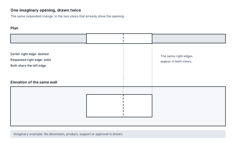
One changed opening, in plan and in elevation
The requested change itself: one opening, drawn once in plan and once in elevation.
- Observe
- Find the dashed earlier right edge and solid requested right edge in each view. Follow their projection links; the left edge stays in place.
- Interpret
- A change to one opening appears in every view that already shows it, which is why a drafter identifies the affected views before redrawing anything.
- Do not infer
- Do not read any dimension, product, support or approval from this figure. No size is shown, and nothing here is decided.
- Try next
- Open a drawing set you have and list the views that would need redrawing after the same request.
Sources and limits for this figure
Original fictional teaching diagram created for this Fieldbook.
The upper view is a plan of one wall, drawn as a band. The lower view shows the same wall in elevation. A solid outline shows the wider requested opening. A dashed vertical line inside it marks the earlier right edge; the left edge stays in place.
Thin projection links connect the earlier and requested right edges at matching horizontal positions in both views. The earlier edge remains visible instead of being covered by the wider outline. This makes the effect of one requested change visible across two drawings.
The line styles are local teaching conventions. Nothing is dimensioned; no lintel, product, fixing, material or approval is represented.
Original fictional teaching diagram created for this Fieldbook; not a surveyed or construction document.
Source and rights:Original fictional teaching diagram
Created for this Fieldbook from chapter 1, 'The opening that moved'. No dimension, product or approval is shown.
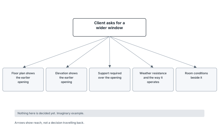
One changed opening and the work it reaches
One requested change, and the separate roles it reaches before anyone decides anything.
- Observe
- Follow the arrows from the wider opening out to each labelled role: the plan, the elevation, the support above, weathering and operation, and the room conditions beside it.
- Interpret
- A change that looks like two moved lines belongs to several people's work at once, which is why a drafter identifies the affected views before redrawing them.
- Do not infer
- Do not read this as a structural solution, an approved instruction or a complete list of everyone a real project would involve.
- Try next
- Name one more view or record in your own project that would need checking after the same request.
Sources and limits for this figure
Original fictional teaching diagram created for this Fieldbook.
The centre of the figure holds the request: a client asks for a wider window. Five arrows leave it. Two reach drawings that already show the earlier opening — the floor plan and the elevation. One reaches the support required over the opening. One reaches weather resistance and the way the window operates. One reaches the room conditions beside it: privacy, daylight, heat gain and any nearby fixture.
The arrows point outward only. They record that a change reaches these roles; they do not show a decision travelling back. A band across the foot of the figure states that nothing here has been decided, authorised or resolved.
No dimension, structural member or product is shown, because the passage this figure accompanies deliberately stops before those choices are made. The project is imaginary and the roles are the ones named in the chapter, not a complete list of everyone a real project involves.
Original fictional teaching diagram — created for this Fieldbook. Its conventions are stated locally; it is not a surveyed or construction document.
Source and rights:Original fictional teaching diagram
Created for this Fieldbook from chapter 1, 'The opening that moved'. Diagram conventions are stated locally; this is not a surveyed or construction document.
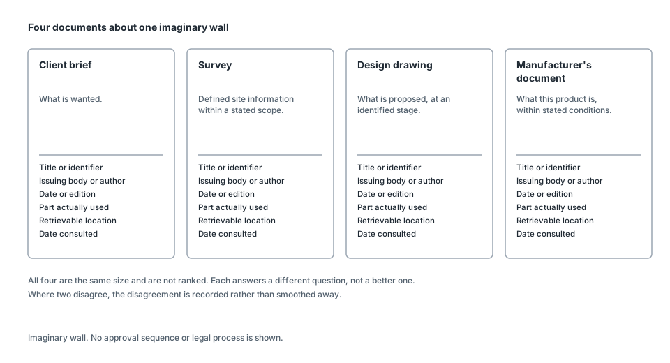
Four documents about one wall
The same wall, described by four documents that answer four different questions.
- Observe
- Read each card’s question, then its source-identification fields. Find the title or identifier and the retrievable location.
- Interpret
- Judging a source means asking whether it is suitable and reliable for the question in hand, and identifying it by title and locator so someone can return to it and check.
- Do not infer
- Do not read this as an approval sequence, a legal process or a ranking that makes one document always better than another.
- Try next
- Take one claim in your notes and record the source using the identification fields shown.
Sources and limits for this figure
Original fictional teaching diagram created for this Fieldbook.
Four cards concern the same imaginary wall. The client brief describes what is wanted. The survey records defined site information within a stated scope. The design drawing describes a proposal at an identified stage. The manufacturer’s document describes a product within stated conditions.
Every card lists six fields: title or identifier, issuing body or author, date or edition, part actually used, retrievable location, and date consulted. These fields help another reader find the document and the relevant part; they do not establish its reliability or suitability.
Equal card sizes do not rank authority. Where documents disagree, record the disagreement and investigate it. No approval sequence, legal process or regulatory pathway is shown. No real product, project or survey is named.
Original fictional teaching diagram created for this Fieldbook; not a surveyed or construction document.
Source and rights:Original fictional teaching diagram
Created for this Fieldbook from chapter 2, sections 'A useful source answers a particular question' and 'Keeping the evidence retrievable'. It is not a legal or approval process diagram.
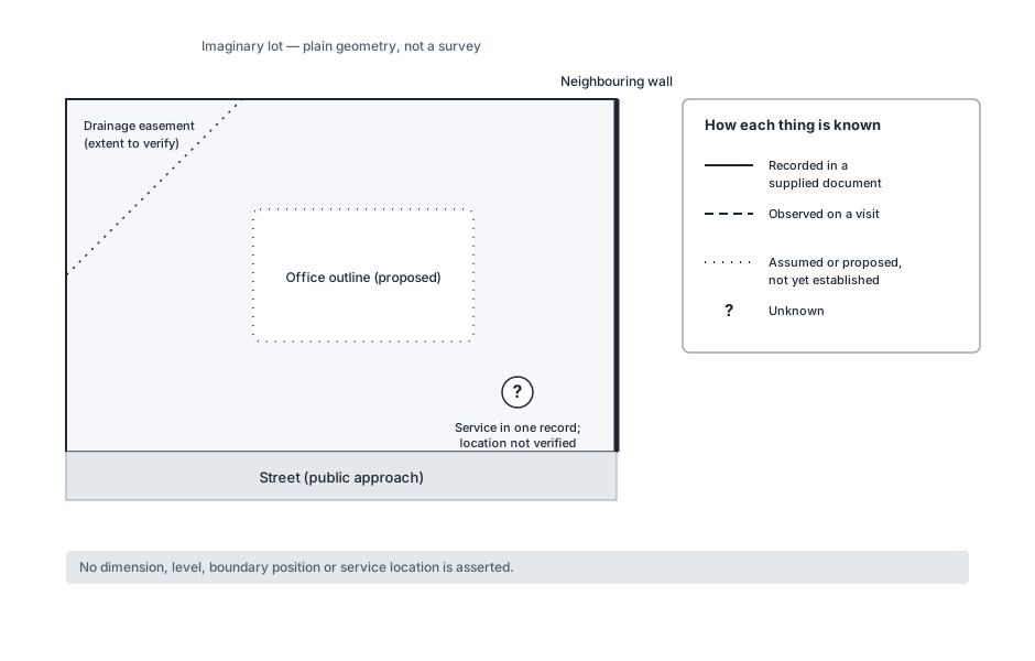
One site record, marked by how each thing is known
One imaginary urban lot with a proposed office on it, each statement marked by how it is known.
- Observe
- Compare the key with the items shown. Which categories are present, and which would need a visit or further records?
- Interpret
- Separating what is recorded from what is assumed shows where the design still depends on investigation rather than evidence.
- Do not infer
- This is not a survey, boundary determination or service location. Verify the legal easement extent against its instrument before relying on it.
- Try next
- Mark up a site plan you already have with the same four categories and see which one grows fastest.
Sources and limits for this figure
Original fictional teaching diagram created for this Fieldbook.
An imaginary urban lot has a public approach at the street and a neighbouring wall recorded in supplied information. A dotted office footprint is a proposed position, not an observed building or an authorised location. A dotted easement extent is tentative and must be checked against the actual instrument.
The key distinguishes recorded information, visit observations, assumptions or proposals, and unknowns. Dotted geometry marks the proposal and tentative extent. A question mark identifies a service recorded in one document whose location is not verified. The dashed observed-on-visit category is explained in the key, but this before-visit example supplies no observed item.
These categories describe how information is known; they do not validate it. No dimension, level, boundary position or service location is asserted, and no real land is depicted.
Original fictional teaching diagram created for this Fieldbook; not a survey, boundary determination or service location record.
Source and rights:Original fictional teaching diagram
Created for this Fieldbook from chapter 4, sections 'A place already connected to other places' and 'Several records of the same land'. It is an illustration of a record, not a record of real land.
The same openings, two intervals
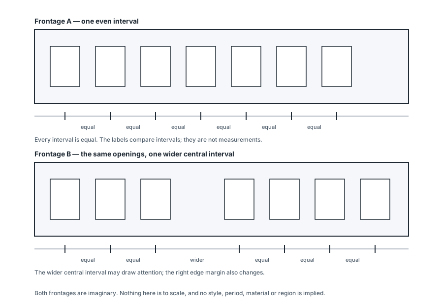
Two imaginary street frontages with the same openings, spaced two different ways.
- Observe
- Compare the repeated intervals in frontage A with the wider central interval in B. Notice that the right edge margin also changes.
- Interpret
- Repetition establishes a rhythm. A wider interval can draw attention to a different part of the composition.
- Do not infer
- Do not read this as a style, a period or a real building. Nothing here establishes what is behind either facade.
- Try next
- Photograph a street you know and mark the intervals between its openings.
Sources and limits for this figure
Original fictional teaching diagram created for this Fieldbook.
Two imaginary facades have the same outer dimensions and seven identical rectangular openings. Frontage A repeats an equal centre-to-centre interval. In B, one central interval increases while the other intervals stay equal. The later openings shift to the right, so the right edge margin also changes.
The marks beneath each facade compare intervals; they are not building dimensions. The wider central interval may draw attention to that part of the composition.
No style, period, material, region or real building is implied. Nothing establishes what lies behind either wall. The plain openings make repetition and variation visible without decorative detail.
Original fictional teaching diagram created for this Fieldbook; not a record of any building.
Source and rights:Original fictional teaching diagram
Created for this Fieldbook from chapter 7, 'Rhythm, emphasis and movement'. No period or style attribution is made.
Used in Chapter 7 · The Grammar and Evidence of Architecture
Three period labels, drawn as bands
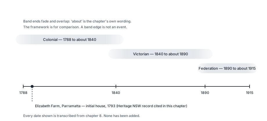
The three period labels this chapter uses, drawn as overlapping bands rather than switches.
- Observe
- Read each band's stated span, then the soft edges where one meets the next, then the single dated marker under them.
- Interpret
- Periods are a framework for comparison; the documented date of one named house sits inside a band without describing every building in it.
- Do not infer
- Do not read the band edges as events, or the framework as a statement about any particular building's date or character.
- Try next
- Find a building you know and decide which band its documented date falls in — and what that still does not tell you.
Sources and limits for this figure
Original teaching diagram created for this Fieldbook from dates stated in chapter 8.
A single horizontal time line carries the three period labels this chapter uses. The Colonial band runs from seventeen eighty-eight to about eighteen forty. The Victorian band runs from eighteen forty to about eighteen ninety. The Federation band runs from eighteen ninety to about nineteen fifteen.
The bands are drawn with faded rather than hard ends, and they overlap slightly where they meet. That is the whole argument of the figure: the word 'about' in the chapter's own wording describes a framework for comparison, and a band edge is not an event.
One dated marker sits below the line: the initial house at Elizabeth Farm, Parramatta, in seventeen ninety-three, as identified in the Heritage NSW record the chapter cites. It is placed to show that a documented date falls inside a band without describing every building in it. No other building is plotted and no additional dates are introduced.
Original teaching diagram — created for this Fieldbook from the dates stated in this chapter. It is not a historical chronology of Australian architecture.
Source and rights:Original teaching diagram of this chapter's stated period framework
Every date shown is transcribed from chapter 8, sections 'Periods overlap with people's lives' and 'A colonial cottage becomes a larger household'. No date, boundary or attribution has been added.
Used in Chapter 8 · Colonial, Victorian and Federation Buildings
A plan label and a household account
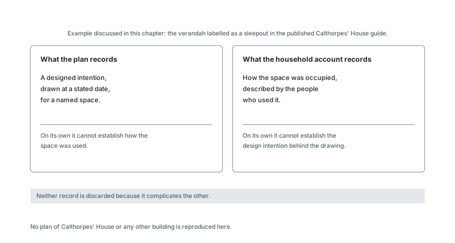
Two kinds of evidence about one room, side by side, with what each can and cannot support.
- Observe
- Read the left column (what a plan label records) against the right column (what a household account records), then the band underneath both.
- Interpret
- Design intention and lived use are different evidence; keeping them apart produces a more accurate description than merging them.
- Do not infer
- Do not read either column as the whole truth about the room, and do not treat this abstract comparison as a plan of any house.
- Try next
- Find a labelled room in a drawing you have and ask what evidence you hold about how it is actually used.
Sources and limits for this figure
Original teaching diagram created for this Fieldbook.
Two columns face each other. The left column is headed 'What a plan label records': a designed intention, drawn at a stated date, for a named space. The right column is headed 'What a household account records': how the space was occupied, described by people who used it.
Under each heading, two short lines state what that evidence supports and what it cannot establish on its own. A plan label cannot establish use. A household account cannot establish the design intention behind the drawing.
A band across the foot of the figure carries the chapter's conclusion: neither record is discarded because it complicates the other, and together they produce a more accurate description than either alone. The case the chapter discusses — the verandah labelled as a sleepout in the published Calthorpes' House guide — is named in the figure as the example, with no plan, room or geometry drawn.
Original teaching diagram — created for this Fieldbook. It is an abstract comparison of two kinds of evidence, not a plan of any house.
Source and rights:Original teaching diagram of two kinds of evidence
Created for this Fieldbook from chapter 9, 'A plan label and actual use'. No plan of Calthorpes' House or any other building is reproduced or reconstructed.
Used in Chapter 9 · From Inter-war Experiments to Contemporary Design
One chain from observation to open question
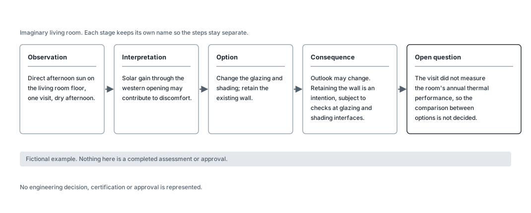
One imaginary living-room problem carried through five stages of a reasoned record.
- Observe
- Follow the single chain across: observation, interpretation, option, consequence, and the open question that still needs an answer.
- Interpret
- The stages belong together but stay visible separately, so a later reader can see which step an argument actually rests on.
- Do not infer
- Do not read this as a completed technical assessment, an approval, or a recommendation for any real room.
- Try next
- Write the same five lines for a decision you are currently carrying in your head.
Sources and limits for this figure
Original fictional teaching diagram created for this Fieldbook.
Five panels are linked in one chain across the figure. The first, Observation, records direct afternoon sun on the floor of an imaginary living room during a single visit on a dry afternoon. The second, Interpretation, identifies solar gain through the western opening as a possible contributor to discomfort. The third, Option, proposes changing the glazing and shading while retaining the existing wall. The fourth, Consequence, notes that this option may change the outlook and that retaining the wall is an intention, subject to checks where new glazing and shading meet the retained construction.
The fifth panel, Open question, is deliberately the widest: the visit has not measured the room's annual thermal performance, so the comparison between options is not yet decided.
Each panel carries its stage name in the same position, so the roles stay visible as separate steps rather than merging into a single recommendation. A footer states that the example is fictional and that nothing shown is a completed technical assessment, an engineering decision or an approval.
Original fictional teaching diagram — created for this Fieldbook.
Source and rights:Original fictional teaching diagram
Created for this Fieldbook from chapter 17, sections 'The recommendation needs a trail' and 'Separate what was found from what it means'. It is not a completed assessment or approval record.
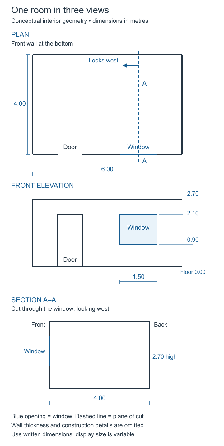
One room in three views
One imaginary room drawn three ways, with the same positions kept across all three.
- Observe
- Find the door and the window in the plan, then find the same two openings at the same left-to-right positions in the elevation.
- Interpret
- Each view answers a different question about one room; reading across them is how a drafter checks that the views agree.
- Do not infer
- Do not measure the screen. The stated dimensions, not the printed size, are the information.
- Try next
- Cover the section and try to predict what the cut will show before you look.
Sources and limits for this figure
Aligned plan, front elevation and section of one fictional room. The section cuts through the front window.
The same room is six metres wide, four metres deep and 2.7 metres high. In plan, the front wall is at the bottom. Measured from its left corner, the door occupies one to two metres and the window occupies 3.5 to five metres.
The front elevation keeps the same left-to-right positions. The door head is 2.1 metres above the floor. The window sill is 0.9 metres above the floor and its head is 2.1 metres above the floor, so the window height is 1.2 metres.
The section plane passes through x = 4.25 metres and looks towards the left side of the plan. The front wall is on the left of the section; the back wall is on the right. The door is outside this cut and is omitted. A dashed blue line and arrow identify the cut and viewing direction in this figure’s own legend.
Wall thickness and construction layers are omitted. The blue marks identify the window and section relationship; they are not an assertion of a universal professional line convention. Use the dimensions and labelled directions, not a ruler on this screen.
Original fictional teaching geometry — Created for this Fieldbook. Diagram conventions are stated locally; these are not surveyed or construction documents.
Source and rights:Original fictional teaching geometry
Created for this Fieldbook. Diagram conventions are stated locally; these are not surveyed or construction documents.
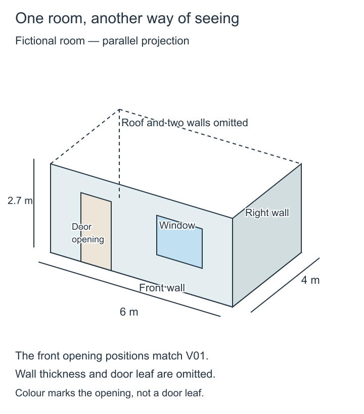
One room, another way of seeing
The same imaginary room again, this time as a single three-dimensional view.
- Observe
- Track width along the front face, depth along the right face and height vertically, then find the V01 door and window.
- Interpret
- A pictorial view connects the three directions at once; the separate plan and elevation still make individual positions easier to compare.
- Do not infer
- Do not read the sloping lines as sloping floors, or the omitted walls and roof as an absence in the room.
- Try next
- Return to V01 and name one thing each view shows that the other cannot.
Sources and limits for this figure
Parallel view of the V01 room with front door and window and right wall visible; roof and two walls omitted.
The front wall contains the same door and window as V01. Follow the width along the front face, the depth along the right face, and the height vertically. The sloping lines are a pictorial projection of horizontal building directions; the floor is not sloping.
This view uses the same six-by-four-metre room and 2.7-metre height. The door and window retain their V01 positions and heights. The roof, left and back wall faces, wall thickness and door leaf are omitted. The dashed upper outline identifies the missing enclosure’s extent.
The coloured door area marks the opening, not a depicted leaf or material. Both the upper dashed outline and rear dashed vertical indicate the omitted model extent. The view helps connect three dimensions, while the separate plan and elevation make selected positions easier to compare. This is a simplified spatial model, not a construction cutaway.
Original fictional teaching geometry — Created for this Fieldbook. Diagram conventions are stated locally; these are not surveyed or construction documents.
Source and rights:Original fictional teaching geometry
Created for this Fieldbook. Diagram conventions are stated locally; these are not surveyed or construction documents.
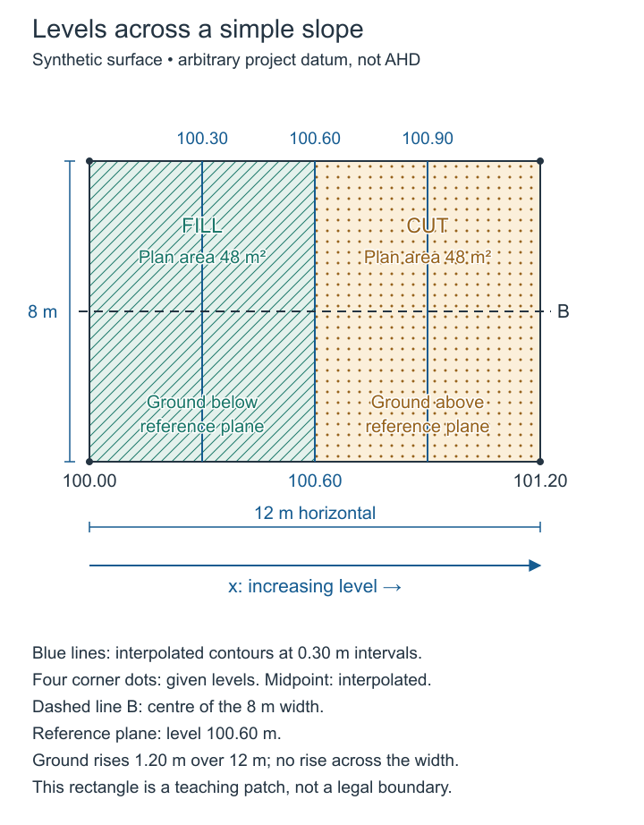
Known levels and an assumed surface
An imaginary twelve-by-eight-metre site with four known corner levels and contours drawn from one assumption.
- Observe
- Find the four corner levels first; only those are data. Then follow the contour lines drawn between them.
- Interpret
- Contours between known points are an interpretation of the surface, so the assumption behind them belongs with the drawing.
- Do not infer
- Do not treat the datum as AHD, the contours as surveyed, or the shaded areas as excavation volumes.
- Try next
- Ask what the contours would look like if the surface were not uniform.
Sources and limits for this figure
Twelve-by-eight-metre fictional site plan with corner levels, straight contours and a central section line.
Only the four corner levels are the starting data: both left corners are 100.00 metres and both right corners are 101.20 metres. The datum is arbitrary, not AHD. The teaching assumption is a uniform surface rising only from left to right.
With that assumption, the 100.30 contour is three metres from the left; 100.60 is six metres from the left; 100.90 is nine metres from the left. The contour interval is 0.30 metres.
The proposed reference plane is 100.60 metres. Its division produces two plan areas of 48 square metres each: fill on the lower half and cut on the higher half. These are horizontal areas, not excavation volumes. Section B follows the marked centre line across the twelve-metre length.
Original fictional teaching geometry — Created for this Fieldbook. Diagram conventions are stated locally; these are not surveyed or construction documents.
Source and rights:Original fictional teaching geometry
Created for this Fieldbook. Diagram conventions are stated locally; these are not surveyed or construction documents.
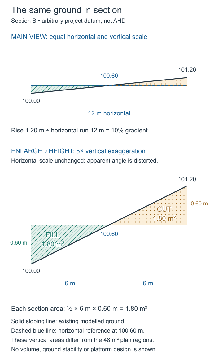
The same site in section
The same imaginary site cut through the middle and drawn as a ground section.
- Observe
- Compare the true-scale section with the labelled five-times-vertical enlargement below it.
- Interpret
- A ten per cent slope looks gentle at true scale; exaggerating the vertical scale makes small differences readable but changes the apparent steepness.
- Do not infer
- Do not read the enlargement as the real profile, and do not take soil behaviour or excavation stability from either drawing.
- Try next
- Work out the rise over a ten-metre run at the same slope before reading the labels.
Sources and limits for this figure
Matching ground section showing a 1.2-metre rise over twelve metres, with equal cut and fill triangles relative to level 100.60.
The main section uses equal horizontal and vertical scales. Rise is 1.20 metres over a horizontal run of twelve metres: ten per cent, or one in ten. Ten per cent is not ten degrees.
The reference level crosses the straight surface halfway along. Each shaded section triangle has a six-metre base and 0.60-metre maximum height. Half multiplied by six multiplied by 0.60 gives 1.80 square metres.
The enlargement uses five times the vertical scale and is explicitly labelled. It makes the triangles easier to see but exaggerates apparent steepness. No soil behaviour, excavation stability, bulking or construction volume is determined by this exercise.
Original fictional teaching geometry — Created for this Fieldbook. Diagram conventions are stated locally; these are not surveyed or construction documents.
Source and rights:Original fictional teaching geometry
Created for this Fieldbook. Diagram conventions are stated locally; these are not surveyed or construction documents.
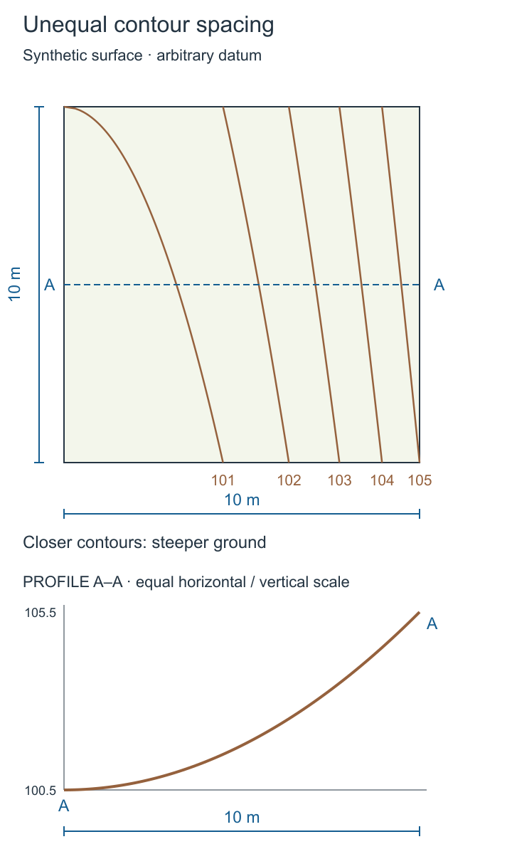
Curved contours and a matching profile
Imaginary curved contours and the matching ground profile taken along one line.
- Observe
- Find where the contour spacing tightens, then find the same position on the profile beneath.
- Interpret
- Spacing is the readable signal of slope: close contours mean a steeper surface along that line.
- Do not infer
- Do not read the curvature as a survey of real ground or the profile as a design level.
- Try next
- Choose a second line across the contours and sketch the profile you would expect.
Sources and limits for this figure
Fictional curved terrain contours above a curved section along the plan’s middle.
The complete mathematical model is z = 100 + 0.05x² + 0.1y, with x and y measured in metres from zero to ten. In plan, x increases rightwards and y upwards from the lower-left corner. All contours and the section come from this declared surface, not from four measured corners.
The contour interval is one metre. The marked section follows y = 5 metres, giving z = 100.5 + 0.05x². Its endpoints are 100.5 and 105.5 metres, and its midpoint at x = 5 is 101.75 metres.
The section uses equal horizontal and vertical scales. Its changing steepness corresponds to changing contour spacing. The average rise/run is five divided by ten, or fifty per cent; local gradient varies. A real site requires sufficient observations and a defensible terrain model.
Original fictional teaching geometry — Created for this Fieldbook. Diagram conventions are stated locally; these are not surveyed or construction documents.
Source and rights:Original fictional teaching geometry
Created for this Fieldbook. Diagram conventions are stated locally; these are not surveyed or construction documents.
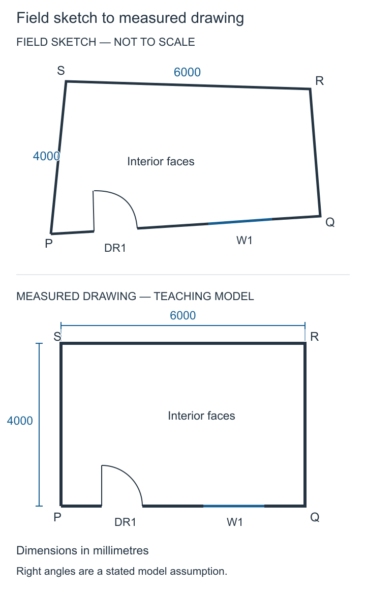
Field sketch to measured drawing
A rough field sketch above the measured plan that was produced from it.
- Observe
- Match each corner name and opening in the sketch to the same item in the measured drawing below.
- Interpret
- A field sketch is a record of what was measured; the measured drawing is an interpretation of it, and the names are what keep the two connected.
- Do not infer
- Do not treat the sketch's proportions as measurements, or the measured drawing as evidence that nothing was missed on site.
- Try next
- Sketch a room you are in and label the endpoints you would need before you could draw it.
Sources and limits for this figure
A rough room sketch above a measured rectangular plan, keeping corner names and openings consistent.
P is the front-left corner, Q front-right, R back-right and S back-left in both records. DR1 identifies the door and W1 the window. The rough sketch is not to scale.
The lower plan uses the fuller fictional dataset: overall interior dimensions 6000 by 4000 millimetres, right angles assumed, door offsets 1000 and 2000 millimetres, and window offsets 3500 and 5000 millimetres from P along the front wall. These opening offsets are additional supplied data; the two overall lengths shown on the rough sketch do not establish them.
The point is the traceable translation from an observed record into geometry. On a real job, opening offsets and squareness need their own measurement and checks. The diagram supplies no evidence of an actual inspection.
Original fictional teaching geometry — Created for this Fieldbook. Diagram conventions are stated locally; these are not surveyed or construction documents.
Source and rights:Original fictional teaching geometry
Created for this Fieldbook. Diagram conventions are stated locally; these are not surveyed or construction documents.
Used in Chapter 5 · Turning Observation into a Measured Record
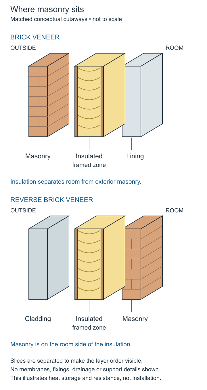
Where the heavy layer sits
The same two wall layers in two arrangements, with the heavy layer on different sides.
- Observe
- Compare where the heavy layer sits relative to the insulation in each arrangement.
- Interpret
- Insulation and thermal mass do different jobs, and the order of the layers changes how the assembly behaves.
- Do not infer
- Do not read either arrangement as a recommended wall build-up or a performance claim for a real project.
- Try next
- Describe which arrangement puts the mass inside the insulated envelope, and say why that matters.
Sources and limits for this figure
Matched wall-layer cutaways comparing exterior brick veneer with room-side masonry in reverse veneer.
In conventional brick veneer, the exterior masonry is separated from the room by the insulated framed zone and lining. In the reverse arrangement shown, the masonry is on the room side of the insulated framed zone.
The room-side masonry can exchange heat with the room more directly. That says where heat storage is accessible; it does not establish a whole-wall R-value or guarantee comfort. Insulation resists heat flow, while mass stores and releases energy.
Read the layer order and inside/outside labels together. Ties, moisture control, fixings, support, fire performance and full junctions are not designed here. These are conceptual assembly comparisons, not interchangeable installation details.
Your Home: brickwork and blockwork
Your Home: thermal mass
Source and rights:Brickwork and blockworkThermal mass
Your Home: Construction systems, Lightweight framing, Brickwork and blockwork, Concrete slab floors and Cladding systems.
Your Home: Thermal mass, Insulation, Glazing and Condensation. Read the assembly and operating conditions as well as the material descriptions.
Used in Chapter 11 · Heat, Moisture and the Building Envelope
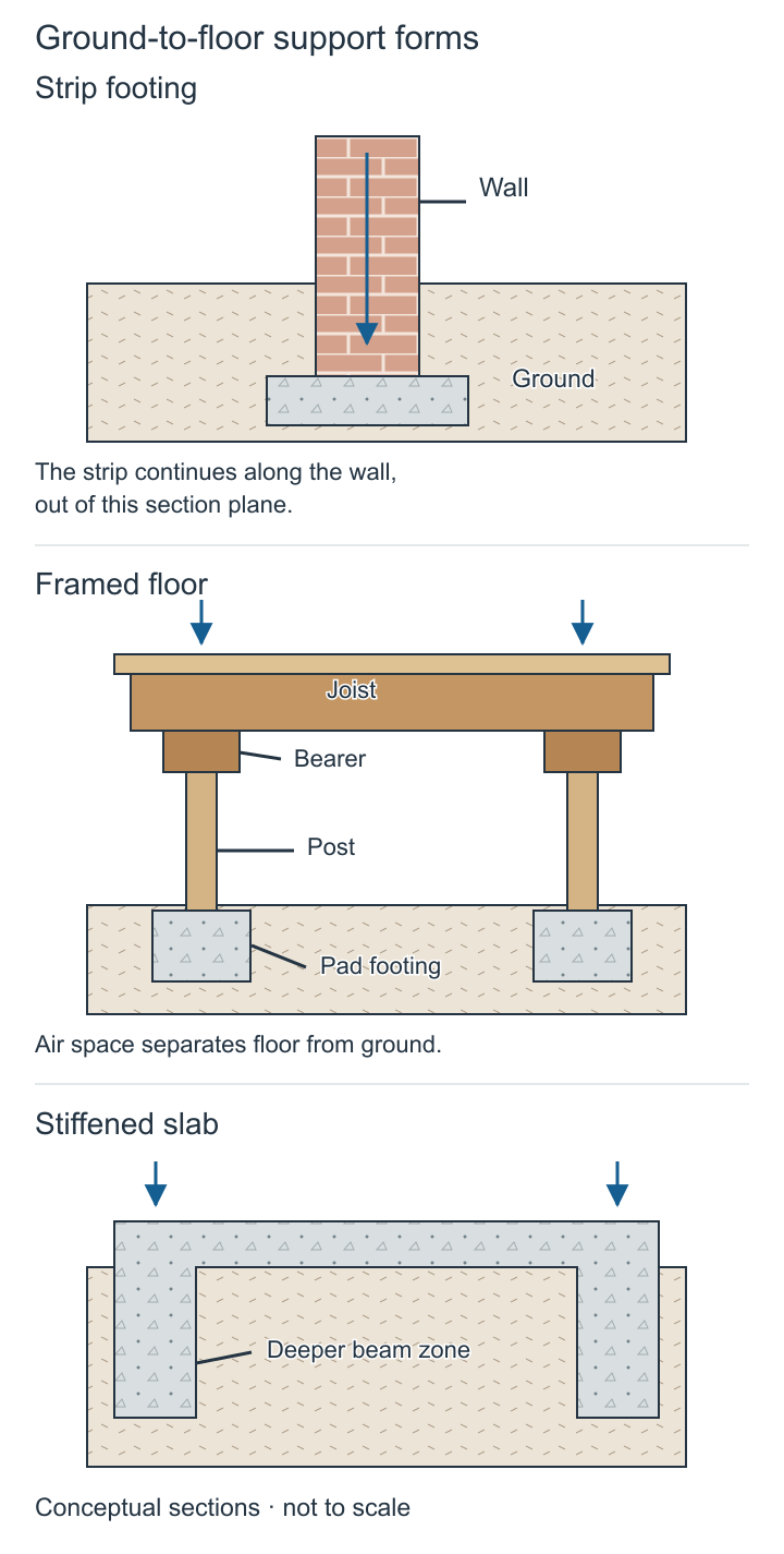
Three ways a floor meets the ground
Three conceptual arrangements show different ways loads reach the ground.
- Observe
- Follow the downward load line in each of the three arrangements until it reaches the ground.
- Interpret
- Each arrangement transfers load through different supported elements before it reaches the ground.
- Do not infer
- Do not read any arrangement as a footing design, a soil assessment or an approved detail. The three are conceptual comparisons and are not drawn to one common scale.
- Try next
- Say what each arrangement would need to be checked against before it could be used.
Sources and limits for this figure
Three conceptual sections: wall on strip footing, joist-and-bearer floor on posts and pads, and slab with deeper edge zones.
The upper section shows a wall transferring load to a strip footing and then the ground. The middle section shows floor joists bearing on a bearer, which transfers load through posts to pad footings. The lower section shows a slab supported at the ground with deeper edge zones.
Look for a continuous sequence of supported parts, rather than treating the floor surface as the entire system. The section through the bearer is an end view; it does not show the complete grid of supports in plan.
These are conceptual forms. Soil suitability, dimensions, reinforcement, connections, internal slab stiffening, damp protection, termite management and engineering design are omitted. The drawings cannot select a footing system for the fictional sites.
NCC 2025 Housing Provisions — Part 4.2 and its application conditions; governing edition still depends on jurisdiction and project.
Source and rights:Housing Provisions
NCC 2025 Volume Two and Housing Provisions. Read an application provision before its detailed pathway. Relevant teaching locations include structural provisions, glazing, fire safety, wet areas, amenity and safe movement.
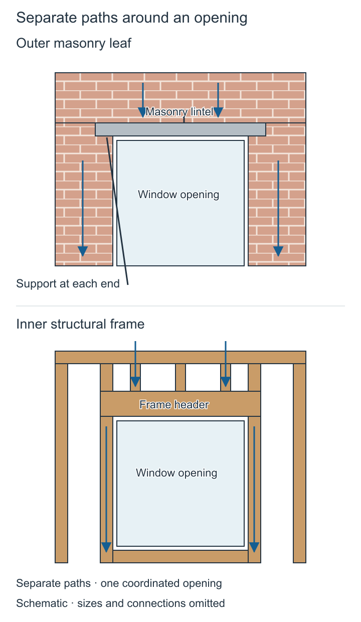
Two openings, two gravity paths
Two openings in an imaginary masonry-veneer wall — one in the masonry leaf, one in the framed leaf — with the separate gravity path above each drawn on its own.
- Observe
- Trace each load path from above the opening down through the wall, and note where the two paths differ.
- Interpret
- Masonry behaves according to its arrangement and support, so an opening changes the wall around it, not only the wall it removes.
- Do not infer
- Do not read the paths as a lintel selection, a structural calculation or a statement about every masonry wall.
- Try next
- Point at the place in each path where a connection would need checking.
Sources and limits for this figure
Matched masonry veneer and timber frame openings with separate lintel and header support paths.
The masonry opening is supported by its lintel and bearings; the framed opening is supported by its header and supporting studs. The openings have the same depicted size, so the comparison isolates the two construction systems.
The arrows show selected downward gravity paths. They are not wind arrows or a complete structural analysis. Continue each path below the drawing to the relevant supporting construction: a line ending at the image edge is not the end of the real load path.
Wall ties, bracing, tie-down, fixings, movement allowances and engineered member sizes are omitted. The window is not being assigned the building load above it.
Your Home: brickwork and blockwork
Your Home: lightweight framing
Source and rights:Brickwork and blockworkLightweight framing
Your Home: Construction systems, Lightweight framing, Brickwork and blockwork, Concrete slab floors and Cladding systems.
Your Home: Construction systems, Lightweight framing, Brickwork and blockwork, Concrete slab floors and Cladding systems.
Used in Chapter 10 · What Structural Materials Can Do, Chapter 13 · Frames, Masonry and Roofs
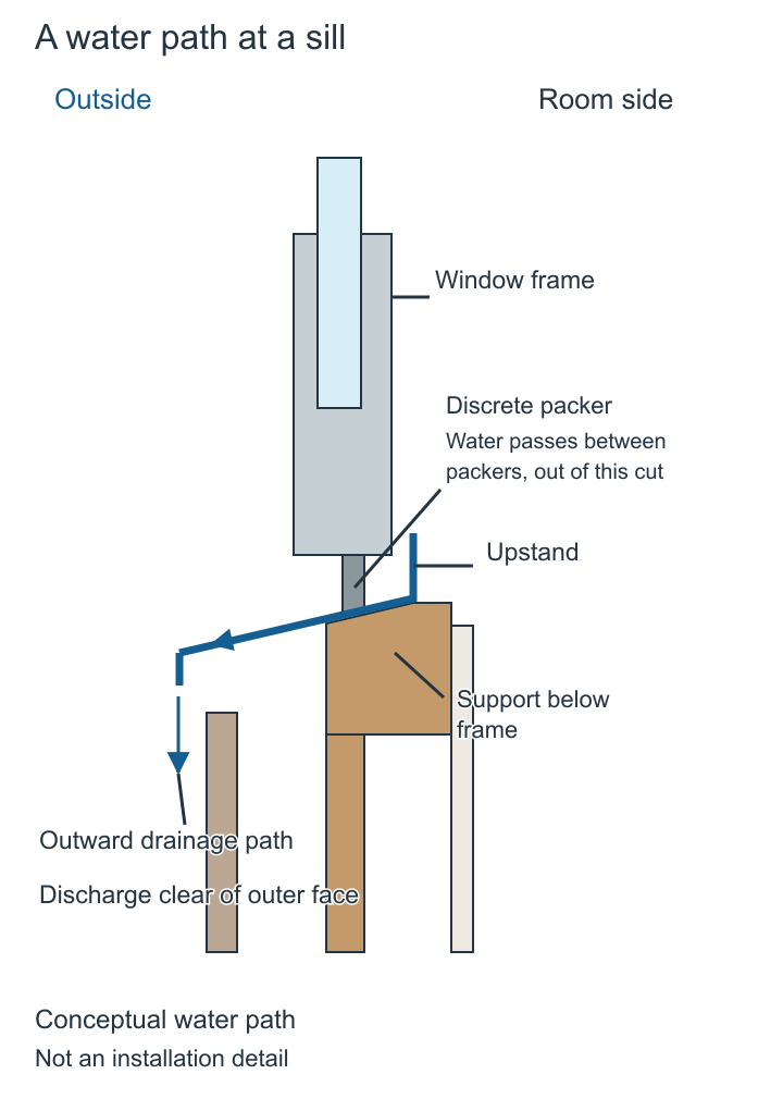
A water path at a sill
A conceptual sill section showing support and an outward-draining receiving surface.
- Observe
- Follow the receiving surface outward. Water passes between discrete packers outside this section cut, not through the solid packer shown.
- Interpret
- Support and drainage must work together; a continuous obstruction would change the drainage condition.
- Do not infer
- This is not an installation detail. The full profile, ends, jambs, seals, fixings and product conditions remain unresolved.
- Try next
- Explain what would change if a continuous support blocked the spaces between packers.
Sources and limits for this figure
Conceptual window sill with raised inner end and an outward fall discharging clear of cladding.
Outside is left and the room is right. Follow the blue receiving surface outward and downward, then beyond the outer face. The upstand rises at its room-side end.
The small support beneath the frame is a discrete packer. Water passes between packers, outside this particular section cut. It does not pass through solid material. A continuous obstruction across that route would change the drainage condition.
This drawing only explains support and drainage relationships. The full window profile, end dams, jamb connections, seals, fixings and product-specific installation are not resolved. It must not be used as an installation detail.
Your Home: cladding systems — Weather management and interfaces; original conceptual figure, not a copied product detail.
NCC 2025 Housing Provisions — Clause 7.5.6 outward drainage at openings; apply its actual conditions. Original conceptual drawing, not a reproduced NCC figure.
Source and rights:Cladding systemsHousing Provisions
Your Home: Construction systems, Lightweight framing, Brickwork and blockwork, Concrete slab floors and Cladding systems.
NCC 2025 Volume Two and Housing Provisions. Read an application provision before its detailed pathway. Relevant teaching locations include structural provisions, glazing, fire safety, wet areas, amenity and safe movement.
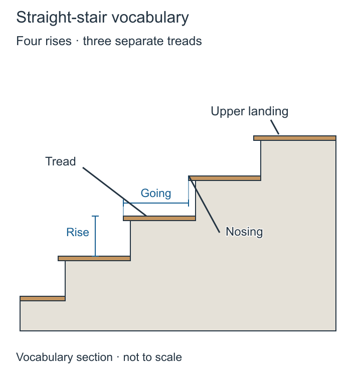
Rise, going and nosing
The named parts of an imaginary stair, drawn so each word has something to point at.
- Observe
- Find rise, going and nosing on the drawing, then say each one out loud while pointing at it.
- Interpret
- Shared vocabulary is what lets a stair be discussed, checked and drawn by different people without confusion.
- Do not infer
- Do not read the proportions as a compliant stair. This figure teaches the words, not the requirements.
- Try next
- Describe the stair nearest to you using the three words.
Sources and limits for this figure
A short conceptual stair section with four rises, three intermediate treads, an upper landing and labelled nosings.
Count four changes between finished levels: lower floor to first tread, then to the second, third and upper landing. There are three intermediate treads because the upper landing receives the fourth rise.
Rise is the vertical difference between successive finished levels. Going is the horizontal distance between successive nosing positions. The projecting nosing makes tread depth and going different measurements.
All four rises are equal in this fictional geometry. No numerical rise or going is selected for construction. Handrails, barriers, headroom, landings beyond the shown edge and applicable conditions require separate design.
NCC 2025 Housing Provisions — Part 11.2 terminology and conditions. Original conceptual drawing; not a reproduced NCC figure.
Source and rights:Housing Provisions
NCC 2025 Volume Two and Housing Provisions. Read an application provision before its detailed pathway. Relevant teaching locations include structural provisions, glazing, fire safety, wet areas, amenity and safe movement.
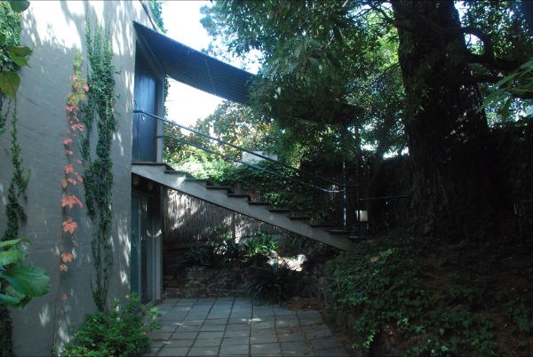
A route outside Walsh Street
A photograph of an outdoor stair beside the wall at Walsh Street, taken in 2012.
- Observe
- Follow the stair from the paved outdoor space up towards the upper doorway, and note the wall and planting beside it.
- Interpret
- An exterior view records one route and one face of a building; the courtyard organisation discussed in the text is not visible from here.
- Do not infer
- Do not read the photograph as the complete circulation, as room names, or as the building at first occupation.
- Try next
- List what you would still need — a plan, a section, an interior view — to describe the arrangement.
Sources and limits for this figure
An outdoor stair beside the wall of Walsh Street, leading towards an upper door with planting nearby.
Follow the visible stair from the paved outdoor space towards the upper doorway. Its relation to the wall and planting can be observed. The photograph does not show the complete interior circulation or establish room names.
This is a later view, photographed on 2 April 2012, not a reconstruction of the house at first occupation. Appearance alone does not establish structural capacity, material specification or present-day accessibility compliance.
Outdoor stair at Walsh Street / Boyd House II, South Yarra. Rebecca D.G, “Boyd House II img stairs.jpg”, via Wikimedia Commons, CC BY-SA 3.0. Photograph reproduced without alteration. Its original supplied size is 600 by 402 pixels.
Rebecca D.G: photograph record
CC BY-SA 3.0 licence
Robin Boyd Foundation: Walsh Street history
Source and rights:Boyd House II img stairs.jpgCC BY-SA 3.0Walsh Street history: Overview
Credit: Rebecca D.G, Boyd House II img stairs.jpg, via Wikimedia Commons, CC BY-SA 3.0. Photograph reproduced without alteration.
Credit: Rebecca D.G, Boyd House II img stairs.jpg, via Wikimedia Commons, CC BY-SA 3.0. Photograph reproduced without alteration.
Walsh Street: custodian account | Robin Boyd Foundation, Walsh Street history: Overview, undated. Read the opening architectural description and the photograph credits separately. |
Used in Chapter 7 · The Grammar and Evidence of Architecture
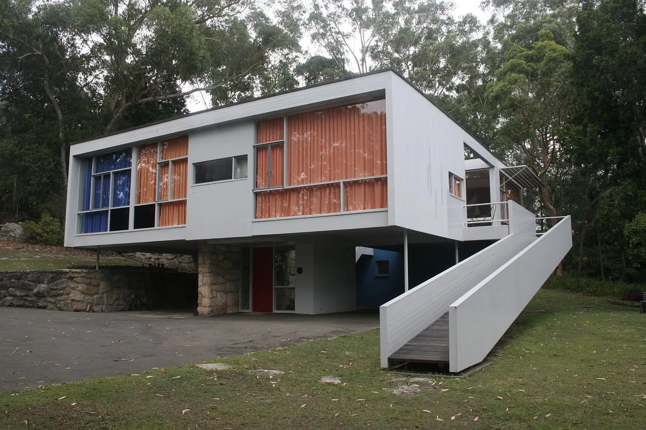
Outside, 2006: Rose Seidler House and its setting
Rose Seidler House seen from outside, showing the glazed face within the whole form and its wooded setting.
- Observe
- Find the broad glazed panels in the upper level, then the ramp rising to the outdoor landing and the stone-faced wall below.
- Interpret
- An exterior view shows where the glazing sits in the building and what surrounds it, which is what an outside view can tell you.
- Do not infer
- Do not infer the complete circulation route, the structural design, the original 1950 condition, component dates, current compliance, or which glazed bay matches any particular interior pane.
- Try next
- Look at the outside form first, then at the living-room view through the glazing in the next photograph, and write down one thing the outside view cannot tell you.
Sources and limits for this figure
Rory Hyde, ‘Harry Seidler, Rose Seidler House- 1950’ / ‘RoseSeidlerHouse.jpg’, photographed 29 December 2006, via Flickr and Wikimedia Commons, CC BY-SA 2.0.
Rose Seidler House from outside, photographed on 29 December 2006. Broad glazing and the surrounding trees can be seen together. Compare this view with the later living-room photograph; the two images show different viewpoints and dates, not matching measured views.
The photograph records a later state of the building, not an original construction record. Planting and fabric may differ from the 2026 interior, and the camera angle and scale differ as well. A white finish hides what is behind it, so the visible surfaces are evidence of appearance on that day and nothing more.
Source and rights:Wikimedia Commons item: RoseSeidlerHouse.jpgOriginating photograph on Flickr: Harry Seidler, Rose Seidler House- 1950Licence deed: CC BY-SA 2.0 Generic
Commons item record, version 1210314889. The ‘1950’ in the photographer’s title is the building’s date, not the photograph’s.
Rory Hyde (Flickr user roryrory), uploaded 19 August 2008, photographed 29 December 2006.
The licence under which this photograph alone is published.
- Photographer
- Rory Hyde
- Photographed
- 29 December 2006
- Licence
- CC BY-SA 2.0 Generic
- This copy
- Re-encoded as a WebP copy at the original 1280 by 853 pixels so the page loads quickly. No resizing, cropping, annotation or other content change. The unchanged original is linked below.
The unchanged original is 1280 by 853 pixels. Open the original file.
Used in Chapter 9 · From Inter-war Experiments to Contemporary Design
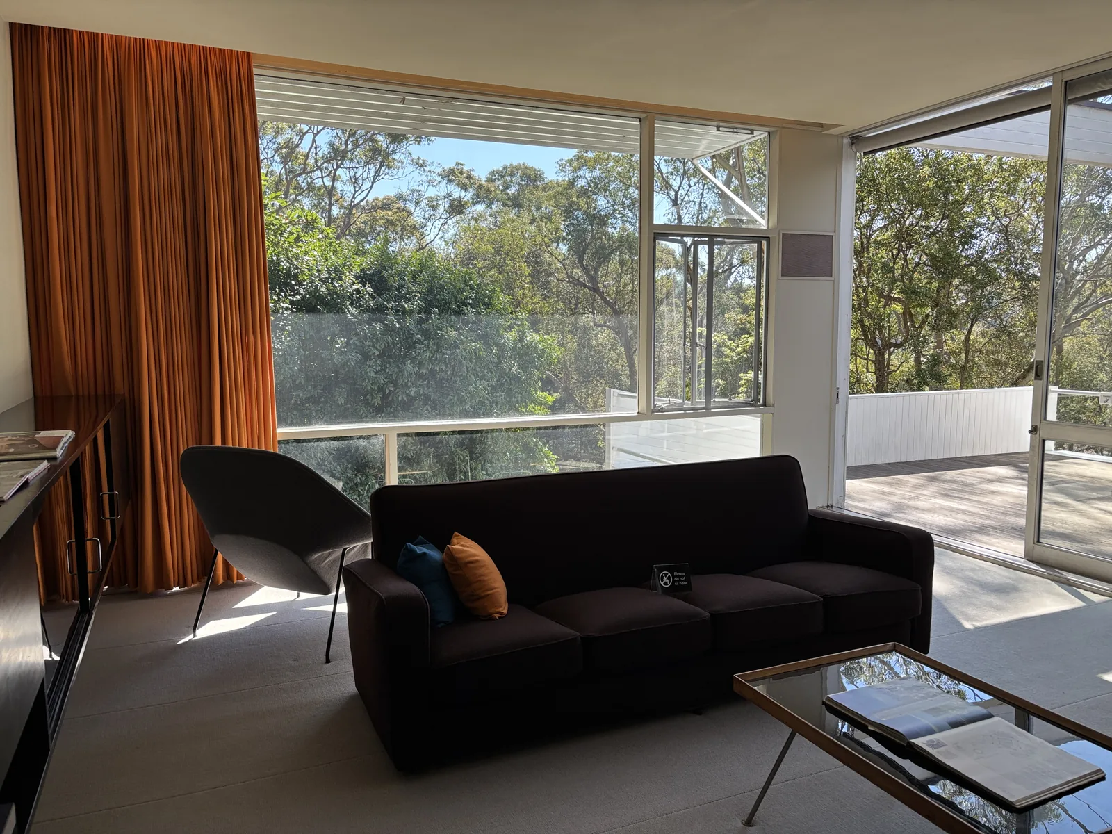
Inside, 2026: the living room and its glazing
The living room at Rose Seidler House, where broad glazing connects the furnished room with trees and the terrace.
- Observe
- Follow the line of sight from the seating, through the glazed wall, to the trees and the terrace beyond.
- Interpret
- You can see a connection from a furnished room out to vegetation and adjacent outdoor space, rather than only reading that it exists.
- Do not infer
- Do not infer the complete plan, functional separation, the room’s condition in 1950, the originality of any finish or furniture, measured dimensions, light levels, thermal performance or accessibility.
- Try next
- Name one relationship visible in this room, then one question the photograph cannot settle.
Sources and limits for this figure
Nick-D, ‘Living room in the Rose Seidler House August 2026.jpg’, 30 August 2026, via Wikimedia Commons, CC BY-SA 4.0.
Inside Rose Seidler House, broad glazing connects the furnished living room with trees and the terrace. This view was photographed on 30 August 2026; it does not show the complete plan or establish the room’s condition in 1950.
The room is in its modern museum display state. The display sign and the books on the table belong to the photographed room today; they are not teaching evidence. The photograph is evidence of the room’s recorded appearance from one camera position, not proof of any other statement in this chapter.
Source and rights:Wikimedia Commons item: Living room in the Rose Seidler House August 2026.jpgLicence deed: CC BY-SA 4.0 International
Commons item record, version 1278733343, uploaded 20 September 2026. The photographer gives the source as own work; the recorded location is photographer-supplied metadata.
The licence under which this photograph alone is published.
- Photographer
- Nick-D
- Photographed
- 30 August 2026
- Licence
- CC BY-SA 4.0 International
- This copy
- Resized to a 1600-pixel-wide WebP copy so the page loads quickly, keeping the original proportions. No cropping, annotation or other content change. The unchanged 4032-pixel original is linked below.
The unchanged original is 4032 by 3024 pixels. Open the original file.
Used in Chapter 9 · From Inter-war Experiments to Contemporary Design, Chapter 15 · Interiors, Finishes and Everyday Use
The written companion notes for these figures
Read the caption with each view. Open the image to enlarge it; use the source drawing when a dimension needs closer examination. Image labels are repeated or explained below at readable text size.
- One room in three views
- One room, another way of seeing
- Known levels and an assumed surface
- The same site in section
- Field sketch to measured drawing
- Curved contours and a matching profile
- Where the heavy layer sits
- Three ways a floor meets the ground
- Two openings, two gravity paths
- A water path at a sill
- Rise, going and nosing
- A route outside Walsh Street
One room in three views
The same room is six metres wide, four metres deep and 2.7 metres high. In plan, the front wall is at the bottom. Measured from its left corner, the door occupies one to two metres and the window occupies 3.5 to five metres.
The front elevation keeps the same left-to-right positions. The door head is 2.1 metres above the floor. The window sill is 0.9 metres above the floor and its head is 2.1 metres above the floor, so the window height is 1.2 metres.
The section plane passes through x = 4.25 metres and looks towards the left side of the plan. The front wall is on the left of the section; the back wall is on the right. The door is outside this cut and is omitted. A dashed blue line and arrow identify the cut and viewing direction in this figure’s own legend.
Wall thickness and construction layers are omitted. The blue marks identify the window and section relationship; they are not an assertion of a universal professional line convention. Use the dimensions and labelled directions, not a ruler on this screen.
Original fictional teaching geometry — Created for this Fieldbook. Diagram conventions are stated locally; these are not surveyed or construction documents.
One room, another way of seeing
The front wall contains the same door and window as V01. Follow the width along the front face, the depth along the right face, and the height vertically. The sloping lines are a pictorial projection of horizontal building directions; the floor is not sloping.
This view uses the same six-by-four-metre room and 2.7-metre height. The door and window retain their V01 positions and heights. The roof, left and back wall faces, wall thickness and door leaf are omitted. The dashed upper outline identifies the missing enclosure’s extent.
The coloured door area marks the opening, not a depicted leaf or material. Both the upper dashed outline and rear dashed vertical indicate the omitted model extent. The view helps connect three dimensions, while the separate plan and elevation make selected positions easier to compare. This is a simplified spatial model, not a construction cutaway.
Original fictional teaching geometry — Created for this Fieldbook. Diagram conventions are stated locally; these are not surveyed or construction documents.
Known levels and an assumed surface
Only the four corner levels are the starting data: both left corners are 100.00 metres and both right corners are 101.20 metres. The datum is arbitrary, not AHD. The teaching assumption is a uniform surface rising only from left to right.
With that assumption, the 100.30 contour is three metres from the left; 100.60 is six metres from the left; 100.90 is nine metres from the left. The contour interval is 0.30 metres.
The proposed reference plane is 100.60 metres. Its division produces two plan areas of 48 square metres each: fill on the lower half and cut on the higher half. These are horizontal areas, not excavation volumes. Section B follows the marked centre line across the twelve-metre length.
Original fictional teaching geometry — Created for this Fieldbook. Diagram conventions are stated locally; these are not surveyed or construction documents.
The same site in section
The main section uses equal horizontal and vertical scales. Rise is 1.20 metres over a horizontal run of twelve metres: ten per cent, or one in ten. Ten per cent is not ten degrees.
The reference level crosses the straight surface halfway along. Each shaded section triangle has a six-metre base and 0.60-metre maximum height. Half multiplied by six multiplied by 0.60 gives 1.80 square metres.
The enlargement uses five times the vertical scale and is explicitly labelled. It makes the triangles easier to see but exaggerates apparent steepness. No soil behaviour, excavation stability, bulking or construction volume is determined by this exercise.
Original fictional teaching geometry — Created for this Fieldbook. Diagram conventions are stated locally; these are not surveyed or construction documents.
Field sketch to measured drawing
P is the front-left corner, Q front-right, R back-right and S back-left in both records. DR1 identifies the door and W1 the window. The rough sketch is not to scale.
The lower plan uses the fuller fictional dataset: overall interior dimensions 6000 by 4000 millimetres, right angles assumed, door offsets 1000 and 2000 millimetres, and window offsets 3500 and 5000 millimetres from P along the front wall. These opening offsets are additional supplied data; the two overall lengths shown on the rough sketch do not establish them.
The point is the traceable translation from an observed record into geometry. On a real job, opening offsets and squareness need their own measurement and checks. The diagram supplies no evidence of an actual inspection.
Original fictional teaching geometry — Created for this Fieldbook. Diagram conventions are stated locally; these are not surveyed or construction documents.
Curved contours and a matching profile
The complete mathematical model is z = 100 + 0.05x² + 0.1y, with x and y measured in metres from zero to ten. In plan, x increases rightwards and y upwards from the lower-left corner. All contours and the section come from this declared surface, not from four measured corners.
The contour interval is one metre. The marked section follows y = 5 metres, giving z = 100.5 + 0.05x². Its endpoints are 100.5 and 105.5 metres, and its midpoint at x = 5 is 101.75 metres.
The section uses equal horizontal and vertical scales. Its changing steepness corresponds to changing contour spacing. The average rise/run is five divided by ten, or fifty per cent; local gradient varies. A real site requires sufficient observations and a defensible terrain model.
Original fictional teaching geometry — Created for this Fieldbook. Diagram conventions are stated locally; these are not surveyed or construction documents.
Where the heavy layer sits
In conventional brick veneer, the exterior masonry is separated from the room by the insulated framed zone and lining. In the reverse arrangement shown, the masonry is on the room side of the insulated framed zone.
The room-side masonry can exchange heat with the room more directly. That says where heat storage is accessible; it does not establish a whole-wall R-value or guarantee comfort. Insulation resists heat flow, while mass stores and releases energy.
Read the layer order and inside/outside labels together. Ties, moisture control, fixings, support, fire performance and full junctions are not designed here. These are conceptual assembly comparisons, not interchangeable installation details.
Three ways a floor meets the ground
The upper section shows a wall transferring load to a strip footing and then the ground. The middle section shows floor joists bearing on a bearer, which transfers load through posts to pad footings. The lower section shows a slab supported at the ground with deeper edge zones.
Look for a continuous sequence of supported parts, rather than treating the floor surface as the entire system. The section through the bearer is an end view; it does not show the complete grid of supports in plan.
These are conceptual forms. Soil suitability, dimensions, reinforcement, connections, internal slab stiffening, damp protection, termite management and engineering design are omitted. The drawings cannot select a footing system for the fictional sites.
NCC 2025 Housing Provisions — Part 4.2 and its application conditions; governing edition still depends on jurisdiction and project.
Two openings, two gravity paths
The masonry opening is supported by its lintel and bearings; the framed opening is supported by its header and supporting studs. The openings have the same depicted size, so the comparison isolates the two construction systems.
The arrows show selected downward gravity paths. They are not wind arrows or a complete structural analysis. Continue each path below the drawing to the relevant supporting construction: a line ending at the image edge is not the end of the real load path.
Wall ties, bracing, tie-down, fixings, movement allowances and engineered member sizes are omitted. The window is not being assigned the building load above it.
A water path at a sill
Outside is left and the room is right. Follow the blue receiving surface outward and downward, then beyond the outer face. The upstand rises at its room-side end.
The small support beneath the frame is a discrete packer. Water passes between packers, outside this particular section cut. It does not pass through solid material. A continuous obstruction across that route would change the drainage condition.
This drawing only explains support and drainage relationships. The full window profile, end dams, jamb connections, seals, fixings and product-specific installation are not resolved. It must not be used as an installation detail.
Your Home: cladding systems — Weather management and interfaces; original conceptual figure, not a copied product detail.
NCC 2025 Housing Provisions — Clause 7.5.6 outward drainage at openings; apply its actual conditions. Original conceptual drawing, not a reproduced NCC figure.
Rise, going and nosing
Count four changes between finished levels: lower floor to first tread, then to the second, third and upper landing. There are three intermediate treads because the upper landing receives the fourth rise.
Rise is the vertical difference between successive finished levels. Going is the horizontal distance between successive nosing positions. The projecting nosing makes tread depth and going different measurements.
All four rises are equal in this fictional geometry. No numerical rise or going is selected for construction. Handrails, barriers, headroom, landings beyond the shown edge and applicable conditions require separate design.
NCC 2025 Housing Provisions — Part 11.2 terminology and conditions. Original conceptual drawing; not a reproduced NCC figure.
A route outside Walsh Street
Follow the visible stair from the paved outdoor space towards the upper doorway. Its relation to the wall and planting can be observed. The photograph does not show the complete interior circulation or establish room names.
This is a later view, photographed on 2 April 2012, not a reconstruction of the house at first occupation. Appearance alone does not establish structural capacity, material specification or present-day accessibility compliance.
Outdoor stair at Walsh Street / Boyd House II, South Yarra. Rebecca D.G, “Boyd House II img stairs.jpg”, via Wikimedia Commons, CC BY-SA 3.0. Photograph reproduced without alteration. Its original supplied size is 600 by 402 pixels.
