

Frames, Masonry and Roofs
Follow openings and loads through frames, masonry and roofs, then examine movement, water paths, eaves and conditional tolerance guidance.
The opening changes the wall
A client asks for a wider view of the garden. On the floor plan, the change seems simple: replace a window with a broad glazed opening. In the building, the wall above that opening still needs support. The roof still receives wind. Bracing, connections, weather protection and the window system all need to be reconsidered.
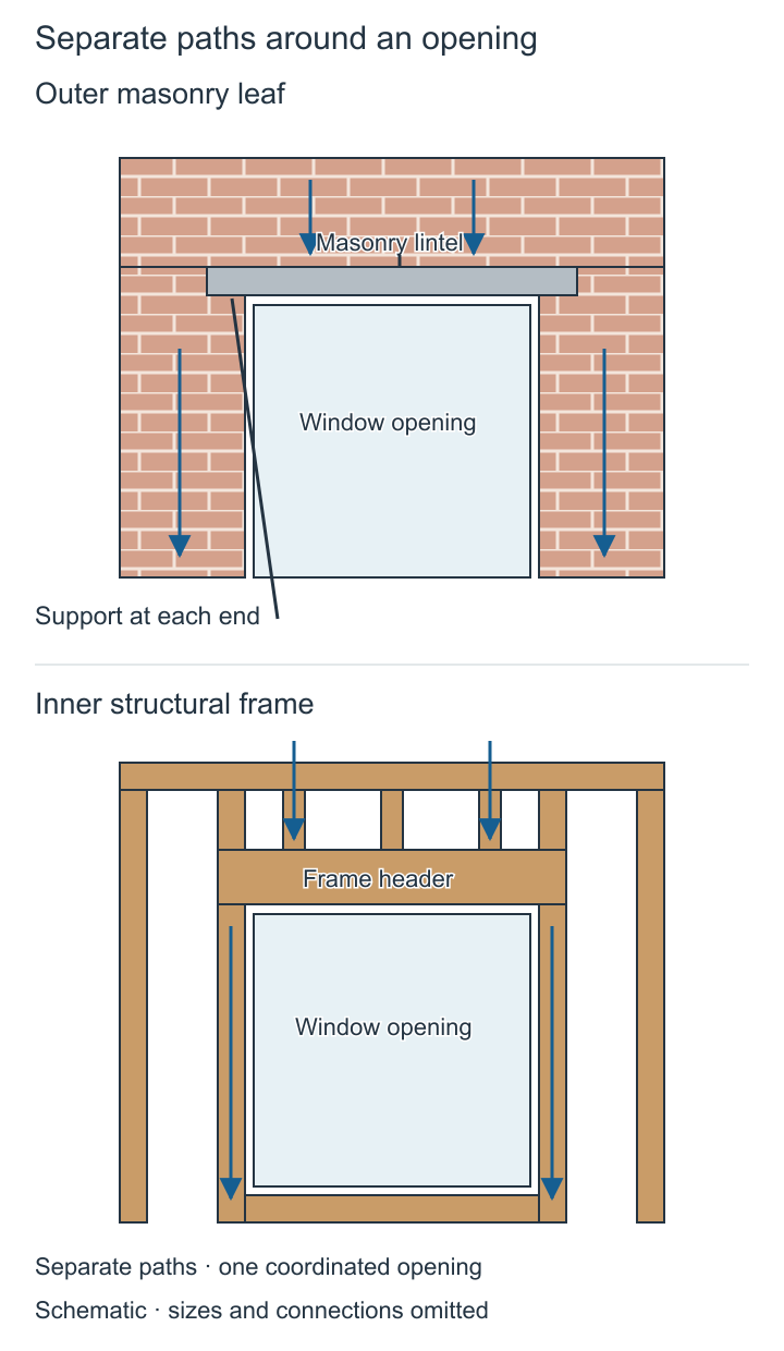
Two openings, two gravity paths
Two openings in an imaginary masonry-veneer wall — one in the masonry leaf, one in the framed leaf — with the separate gravity path above each drawn on its own.
- Observe
- Trace each load path from above the opening down through the wall, and note where the two paths differ.
- Interpret
- Masonry behaves according to its arrangement and support, so an opening changes the wall around it, not only the wall it removes.
- Do not infer
- Do not read the paths as a lintel selection, a structural calculation or a statement about every masonry wall.
- Try next
- Point at the place in each path where a connection would need checking.
Sources and limits for this figure
Matched masonry veneer and timber frame openings with separate lintel and header support paths.
The masonry opening is supported by its lintel and bearings; the framed opening is supported by its header and supporting studs. The openings have the same depicted size, so the comparison isolates the two construction systems.
The arrows show selected downward gravity paths. They are not wind arrows or a complete structural analysis. Continue each path below the drawing to the relevant supporting construction: a line ending at the image edge is not the end of the real load path.
Wall ties, bracing, tie-down, fixings, movement allowances and engineered member sizes are omitted. The window is not being assigned the building load above it.
Your Home: brickwork and blockwork
Your Home: lightweight framing
Source and rights:Brickwork and blockworkLightweight framing
Your Home: Construction systems, Lightweight framing, Brickwork and blockwork, Concrete slab floors and Cladding systems.
Your Home: Construction systems, Lightweight framing, Brickwork and blockwork, Concrete slab floors and Cladding systems.
The opening is a useful way into construction methods because it reveals how a building works around an interruption. A solid-looking wall may combine a frame, insulation, membranes, a cavity, cladding and lining. Each layer must deal with the opening in its own way.
A frame provides a connected arrangement of members. In a common wall frame, vertical studs sit between horizontal plates. Members around openings transfer the loads assigned to them. Their sizes and connections depend on the designed system. Recognising their names helps a reader follow the drawing, but does not enable member selection by appearance.
A lintel spans over an opening and transfers load to supports at its ends. The support beneath each end matters as much as the lintel itself. Enlarging the opening may reduce available support or move concentrated loads to new positions. Those loads must continue through the floor and footing system.
Gravity, sideways force and uplift
Gravity loads travel down through the connected structure. Wind adds actions in other directions. It can push and pull on surfaces, produce lateral forces and create uplift. A house therefore needs more than enough material beneath its roof to carry weight.
Picture an open rectangular frame with flexible corners. Pushing sideways can distort it into a leaning shape. A suitable bracing system resists that distortion and transfers forces into connected supports. The purpose is stability under the relevant actions, not simply keeping the frame straight while it is photographed.
Bracing can take different forms, including designed diagonal elements or sheet systems with specified fixings. A sheet that happens to cover a wall is not automatically a bracing panel. The material, geometry, fastenings, edge connections and anchorage determine its assigned performance.
Roof and floor planes may act as diaphragms, transferring lateral forces towards bracing elements. A diaphragm is a structural assembly that carries forces within its plane. Its edges, openings and connections are part of that function. The word describes a role, not a guarantee provided by every sheeted surface.
Tie-down provides a connected path for uplift forces. Roof elements connect to walls, which connect through the floor or subfloor to the supporting structure and ground. A strong connection near the roof is not enough if the path stops lower down. The entire sequence needs to work together.
Wind classification is a design input distinct from soil classification. Its applicable method considers the site's wind exposure and the building conditions within that method's scope. The classification or design information used for framing and connections must belong to the actual proposal. A sheltered appearance during one visit does not establish it.
Imagine two document entries: a site report describing reactive ground, and wind-design information for the proposed house. The first informs movement and footing questions. The second informs wind actions and the construction selected to resist them. Changing the building's height or exposure assumptions may require the wind information to be revisited even if the soil report remains unchanged. The drafter's task is to recognise and refer that changed input, rather than assign a wind class from intuition.
This explains why the garden opening can affect more than the lintel. The removed wall portion may have been part of a bracing arrangement. A remaining narrow pier may receive greater demand. The designer needs to identify the original structural function before deciding how the altered wall will perform.
Temporary bracing addresses construction stages before the permanent arrangement is complete. A frame may need support before roof and wall systems are fixed. Removing temporary bracing because the frame appears upright confuses a momentary position with stability under expected actions.
A wind classification carries its inputs with it
In housing wind guidance, N2 is a non-cyclonic wind classification. The number identifies the class used for structural design; it is not itself a wind speed.
The same Avium report lists wind region, terrain, topography and shielding inputs alongside its N2 result under the standard edition used in 2020. N2 is a reported project input here, not a classification calculated by this book. Reading those inputs explains why the result cannot be transferred to another site merely because its proposed house looks similar.
Framed walls and masonry walls
Timber and light steel frames can organise building loads around a network of relatively slender members. Their cladding and lining may perform other functions or contribute specified structural roles. The complete system must be identified before deciding which component carries which action.
Loadbearing masonry uses the masonry assembly to support assigned building loads. Openings need suitable support above them. Slender portions, intersections and connections need restraint. The wall's appearance does not disclose all these relationships, especially where reinforcement or ties are concealed.
In cavity masonry construction, two leaves are separated by a cavity. A leaf is a thickness or layer of masonry. The arrangement and role of each leaf must be established from the design. The cavity, connections and water-control details are part of the system; it is not simply twice the strength of one wall.
In brick veneer, the masonry skin works with a separate frame. The veneer carries its own assigned loads and requires support and ties. The frame performs the structural roles given to it. A section is often the clearest way to see why a brick exterior and a loadbearing brick wall are different constructions.
Masonry support around openings must be coordinated with the frame and window. A masonry lintel may support an outer leaf while another element supports loads in the frame. One visible lintel does not necessarily perform both jobs. Reading all the layers prevents an incomplete load-path explanation.
Follow the two paths around a hypothetical veneer opening. In the outer leaf, masonry above the opening loads its lintel. That lintel transfers force into the masonry supports at its ends and onward to their support below. In the inner frame, the roof loads assigned above the opening reach a header or lintel and then the supporting frame members at its ends. They continue through the relevant floor and footing system.
The window occupies the opening within those surrounding paths. It resists its own specified actions, including wind, without becoming an unintended prop for the roof or masonry. Widening the opening changes both support arrangements. Coordination requires the outer and inner paths to be resolved, even where the finished trim conceals their separation.
Reinforced masonry introduces reinforcement and grout in specified locations. Their continuity and anchorage matter where forces transfer through the wall and into its supports. The drawing may need sections and schedules because the reinforcement cannot be fully explained by an exterior elevation.
Movement happens after the drawing is finished
Buildings move under load and as materials respond to moisture and temperature. Some changes occur early; others repeat with seasons or daily conditions. Adjacent systems can move differently. A detail must accommodate the relevant movement while maintaining its other duties.
A window under a supporting member illustrates the problem. The structure above may deflect or settle within its designed behaviour. The window needs an installation relationship that prevents unintended building loads from bearing on it. Packing, fixing and clearances must suit the actual frame and structural conditions.
An articulation joint in masonry helps accommodate specified movement. Its location affects the wall's behaviour and appearance. A joint is not a missing strip of mortar awaiting correction. The finish and seal must preserve its intended function.
Shrinkage control in concrete and movement accommodation in masonry are related design concerns but use different details. Calling both a crack-control joint does not make their construction interchangeable. The relevant drawing and specification should identify the joint's purpose and system.
Movement also affects brittle finishes and junctions between old and new work. A rigid finish spanning an intended separation can crack. A flexible-looking material may have limited movement capacity. The design needs the expected movement and the product's capability to be compatible.
Roof shape and roof structure
A roof plan shows the roof from above. An elevation shows its visible outline from outside. A section explains its relationship to the rooms and supporting structure. These views answer different questions, and none should be asked to supply information absent from it.
A gable roof has sloping planes meeting at a ridge, with a gable at an end. A hip roof has sloping surfaces at its ends as well. A skillion has a single main slope. These basic forms can be combined. Their shapes influence water collection, shading and the space beneath them.
The roof covering sheds weather. The roof structure carries assigned loads and transfers them to supports. Battens or other support members may connect the covering to rafters, trusses or another structural system. The exact arrangement depends on the selected construction.
A rafter is a sloping structural member in a roof arrangement. A truss is a connected framework of members that works as an engineered assembly. Its outer members are chords; its internal connecting members are webs. The webs transfer forces between parts of the framework, allowing the whole assembly to work through its designed geometry and connections. Removing an inconvenient web changes that behaviour even when the outer triangular outline remains.
Roof pitch describes the slope of the roof surface. The suitable pitch for a particular covering depends on the product and its installation conditions. A roof that looks almost flat may still have a designed fall. A visual impression from an elevation is not an adequate substitute for the specified geometry.
Changing roof coverings can change permanent load, fastening needs and other conditions. Replacing one material with another therefore needs more than a colour approval. The supporting structure and the whole roof assembly need to suit the change.
Roof water needs a continuous route
Rain first reaches the roof catchment. The roof directs it towards collection points. Gutters and downpipes convey it onward. A suitable discharge system completes the route. Each part must be considered with the amount of water and the geometry contributing to it.
A valley collects water from adjacent sloping roof planes. Its flow can be more concentrated than runoff from a small isolated roof surface. A lower roof receiving discharge from above has an additional contribution. The outline of the lower roof alone does not describe its water load.
Eaves gutters run near the lower edge of a roof. Their position can make an external overflow route possible, but the actual levels and details determine what happens. An overflowing gutter must not be assumed to spill safely away from the building merely because it is visible from outside.
A box gutter is often located within or between roof forms, where overflow can have serious consequences for the enclosed building. Collection, outlets and emergency overflow need coordinated design. The Housing Provisions' simplified roof-drainage solution excludes box gutters. Recognising that boundary prevents a reader from extending a familiar eaves-gutter rule into a different system.
The support beneath the channel must preserve its intended geometry. Sagging or movement can create a low point away from an outlet, leaving water where the design intended it to flow onward. The channel, outlet and overflow levels must be considered together. Support spacing, falls and capacity belong to the applicable design rather than this conceptual explanation.
Drainage design considers specified rainfall events and consequences. A system may need to address a more severe event for overflow than for its ordinary collection capacity. A downpipe symbol on a roof plan does not show that those calculations have been completed.
Imagine a new upper-storey extension whose roof drains onto the existing lower roof. The lower roof and gutter now receive water from a larger combined catchment. Leaving their original dimensions unchanged is a design decision that requires evidence. The building's water path has changed even if the old roof itself has not been rebuilt.
Eaves and the underside of the roof
An eave is the part of a roof projecting beyond the wall. It can shade windows and shelter parts of the wall. Its effectiveness depends on orientation, projection and the relevant sun or rain conditions. An eave that helps one façade may behave differently on another.
The soffit is an underside surface, often the lining beneath an eave. It needs suitable support and fixing for its material and exposure. Wind can act on this surface. A lining schedule must therefore identify more than a colour and sheet thickness.
Roof ventilation, insulation and eaves details need coordination. A required air path can be obstructed by insulation placed without regard to the junction. Conversely, an opening added for ventilation may affect weather, pest or bushfire protection. The detail must maintain the intended combination of functions.
Eaves do not automatically remove the need for flashing over every opening. Protection depends on actual geometry and the applicable system. A sheltered-looking window can still receive wind-driven rain. The opening must be read as part of the whole wall and roof arrangement.
Tolerances describe particular departures
A tolerance is a permitted departure from a specified dimension, position or condition under a stated rule. It is different from an instrument's measurement capability. A laser's display resolution does not tell the reader how much wall bow is acceptable.
The measurement method matters. Bow, plumb and level describe different relationships. Bow concerns curvature away from a reference. Plumb concerns vertical alignment. Level concerns horizontal alignment. A wall can be straight in one direction while leaning, or vertical at its ends while bowing between them.
A Queensland example shows why conditions belong with the number. The Queensland Building and Construction Commission's December 2023 guide addresses wall bow exceeding four millimetres within any two-metre length during the first twelve months after completion. Its scope, measurement provisions and precedence rules qualify that statement. The guide identifies an NCC 2022 baseline and is not a national NCC 2025 tolerance rule.
The same guide does not allow a reader to reduce the allowance proportionally for a shorter measurement length. That condition changes how the number is used. Quoting only four millimetres loses the method, time and jurisdiction that make the example meaningful.
An observed result near a limit also needs reliable measurement. Repeating the same reading can reveal consistency, but cannot remove a systematic error caused by an incorrect reference. The uncertainty of the observation and the permitted departure answer separate questions.
A tolerance finding does not establish every aspect of performance. A wall within a bow allowance may still have a moisture or structural problem. A wall outside an appearance tolerance is not automatically about to collapse. The relevant condition must be assessed for the question being asked.
Following a change through the building
Return to the wider garden opening. The architectural change affects the view and the room's connection to outside. Structurally, it changes the opening, support and perhaps bracing. Thermally, it changes glazing and shading. For weather protection, it changes flashings and drainage at the frame.
The drawing set should allow those relationships to be followed. A revised plan identifies the opening. Elevations and sections locate it vertically. A schedule identifies the window assembly. Structural and installation information resolve support and fixing. Relevant specifications describe the selected systems and their conditions.
The work of interpretation is to keep those descriptions connected. A roof, frame or masonry wall is not a collection of independent products. Its behaviour emerges from the arrangement, the connections, the construction sequence and the surrounding conditions. Understanding those relationships makes a proposed change easier to examine and discuss accurately.