
Reading a Coordinated Drawing Set
Follow window tags, dimensions and levels across actual house drawing extracts, then examine how consultant drawings expose coordination questions.
Begin with what was issued
A drawing set describes one proposal through many views and documents. Coordination means those descriptions agree where they meet, or clearly identify the decisions still to be resolved. Possessing every page in a download does not establish that the proposal is fully coordinated.
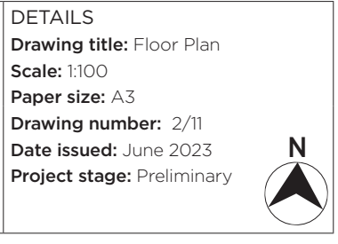
Banksia — Actual Details titleblock extract — sheet 2
The actual titleblock on the first Banksia sheet this chapter uses.
- Observe
- Read the four document facts printed here: the drawing name, the drawing number, the date and the status.
- Interpret
- A titleblock tells you what the sheet claims to be, which is the first thing to establish before reading anything drawn on it.
- Do not infer
- Do not read these facts as a revision history, a construction approval or a guarantee that the set is complete.
- Try next
- Find the same four facts on any drawing you are given this week.
What this sheet states about itself
- Pack
- Banksia (Brisbane)
- Sheet
- Sheet 2 of 11
- Drawing
- Floor Plan, drawing 2/11
- Issue
- Preliminary issue, June 2023 — a preliminary house-design guide, not project-approved construction documentation.
- Scale
- This titleblock states 1:100 at A3. That is a fact about the printed sheet: the screen extract shown here is not to scale and must not be measured.
- Revision
- Revision not stated in the source. The supplied issue is Preliminary, June 2023.
Sources and limits for this figure
Actual Design For Place drawing extract.
© Commonwealth of Australia 2026. Design For Place, CC BY 4.0. Supplied free at Your Home. This extract is cropped from the source drawing; its remaining content has not been redrawn or corrected. Source logos and the Commonwealth Coat of Arms are excluded. No endorsement is represented.
Read this extract with the original source pack and the drawing companion. It is a preliminary example, not project-approved construction documentation. The screen image has no fixed drawing scale.
Source and rights:Banksia technical drawings
The Banksia technical drawings contain the principal June 2023 set followed by four older alternative sheets. The Telopea technical drawings contain twelve June 2023 sheets. Read them with the corresponding Banksia Design Options and Telopea Design Options.
This chapter follows real published examples. The first two are the Commonwealth's Design For Place house designs, Banksia and Telopea, for Brisbane. They provide accessible architectural drawings with plans, elevations, sections and schedules. Their technical sheets are preliminary designs issued in June 2023. They are teaching examples of documentation, not approved designs for a reader's site.
The visual companion provides selected extracts and links to the source drawings. Use it for the close reading in this chapter. Narration can explain the route through the information, but it cannot show you how a line, symbol or dimension connects to the drawn object. Those relationships need to be seen.
Start with the titleblock, the area of the sheet identifying the drawing and its issue information. Banksia's floor plan is drawing two of eleven. It states the drawing title, intended paper size, scale, location, date and preliminary stage. It also directs the reader to the companion Design Options document.
Two of eleven identifies the sheet within that architectural pack. It is not revision two. June 2023 identifies the stated issue date. It is not the date of a site survey. The word Preliminary describes the stage and limits how the information should be used.
The downloaded Banksia file contains fifteen pages, which creates an instructive trap. Its first eleven sheets form the current published preliminary pack. Four later PDF pages are older alternative designs dated March 2020. Their notices say they have not been updated for the stated NCC 2022 changes. They have no associated estimated Nationwide House Energy Rating Scheme ratings, often called NatHERS ratings.
Page order has therefore not created a single current design. The alternatives must remain identified as alternatives. Combining their roof or room arrangement with the main design without review would create a new, unresolved proposal. A reader who checks only the PDF's page count misses that distinction.
Reading the Design For Place drawings
Reading the Design For Place drawings
Use these extracts with chapter 16. Begin with the actual titleblock, then the floor plan, schedule and relevant elevation or section. Every large drawing can be opened at its full supplied pixel size; the original PDF remains the scalable source. Do not measure screen distances as construction dimensions.
Source packs and their limits
The Banksia technical drawings contain the principal June 2023 set followed by four older alternative sheets. The Telopea technical drawings contain twelve June 2023 sheets. Read them with the corresponding Banksia Design Options and Telopea Design Options.
These are preliminary house-design guides. They are not a complete, project-approved construction set and do not supply a coordinated survey, engineer's design and services package. The source's disclaimer applies. The two Brisbane examples do not set the jurisdiction for the whole Fieldbook.
A first route: Banksia's window
The titleblock says Floor Plan, drawing2/11, June 2023 and Preliminary. It also states1:100 at A3. Those are document facts, not a revision history or construction approval.
On the floor plan, find W2 and W3. Then move to the schedule extract. It labels W3 as mirrored. The full schedule legend identifies FG as fixed glass and CW as casement sash; use the actual legend rather than guessing from a diagonal line.
The schedule's W2/W3 overall width is 2650 millimetres, divided into 1800 and 850. Its height is 1500, above a900-millimetre sill height measured from the shown ground finished-floor datum. The addition900 +1500 gives the2400-millimetre head level. These relationships are clearer in the focused crop than in a reduced whole sheet. Mirroring swaps the arrangement's handedness; it does not change its total width.
Return to the plan to recover location. The schedule alone cannot tell you where in the house the item belongs. Compare the east elevation and sections for the building's vertical relationships, then the setout plan for dimensions. A tag, a dimension and a level each answer a different question.
A second route: Telopea across two storeys
Start with the ground and upper floor plans. Follow the stair and the rooms it connects, then open Section AA. The section shows room height and the intervening floor construction as different relationships. A2700-millimetre ground-floor ceiling height is not automatically the floor-to-floor height. The upper-floor setout and window schedule provide other information that the furnished plan leaves out.
The schedule's lower row includes upper-window identifiers such as W6, yet its level line is labelled GROUND FFL. Read that label alongside the floor plans and section, and preserve the query discussed in chapter 16. Do not silently rename the datum while interpreting the drawing. The complete crop retains both the identifier and label so that the issue can actually be examined.
Credits for every drawing extract
© Commonwealth of Australia 2026. Design For Place is licensed under CC BY 4.0, and provided free of charge at Your Home.
The extracts are cropped from the linked technical drawings. Cropping removes margins and unrelated titleblock material; the remaining drawing content has not been redrawn or corrected. The focused window, titleblock and legend images are additional crops from the same sources. Source logos and the Commonwealth Coat of Arms are outside the extracted regions. No government endorsement is represented.
See Your Home copyright and exclusions. The image licence does not make the example suitable for a particular building site.
Banksia: recognise the house before measuring it
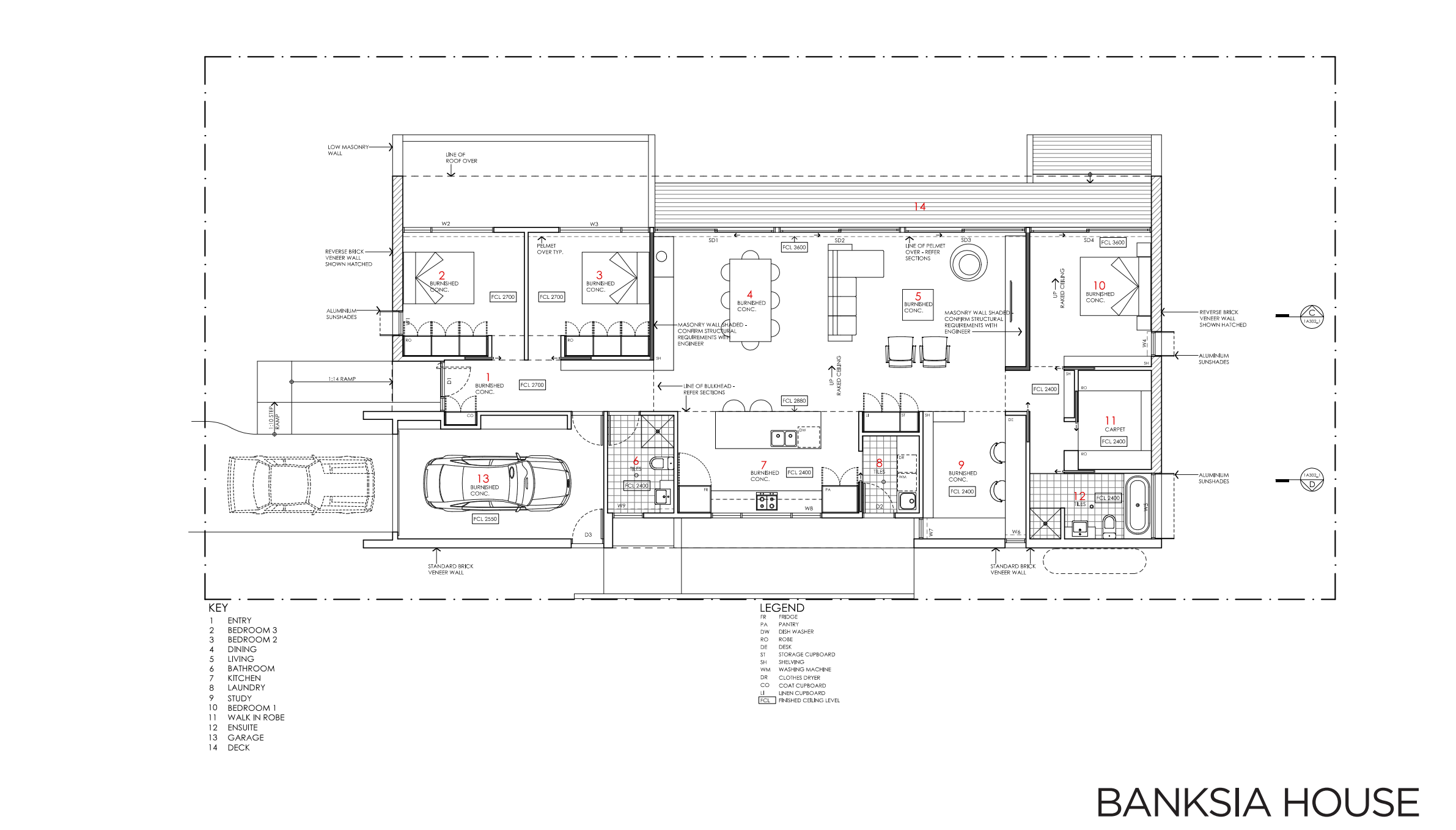
The furnished floor plan uses numbered spaces and a room key. Entry is one; dining is four; living is five; kitchen is seven. The numbers identify spaces rather than dimensions. The furniture helps the reader understand intended use and circulation.
Banksia — Floor plan — sheet 2
The Banksia floor plan, the sheet that tells you where everything else belongs.
- Observe
- Walk the plan once before measuring anything: entry, living spaces, wet areas, then the window tags along the outside walls.
- Interpret
- Recognising the house first is what makes every later sheet readable, because tags and dimensions only mean something in a located house.
- Do not infer
- Do not measure the screen image, and do not treat a preliminary guide plan as approved construction documentation.
- Try next
- Find W2 and W3 on this plan before you open the schedule.
What this sheet states about itself
- Pack
- Banksia (Brisbane)
- Sheet
- Sheet 2 of 11
- Drawing
- Floor Plan, drawing 2/11
- Issue
- Preliminary issue, June 2023 — a preliminary house-design guide, not project-approved construction documentation.
- Scale
- The source sheet states 1:100 at A3. What is shown here is a selected screen extract of that sheet and is not to scale; do not measure it. Open the source pack to read its full dimensions, notes and scale instructions.
- Revision
- Revision not stated in the source. The supplied issue is Preliminary, June 2023.
Sources and limits for this figure
Actual Design For Place drawing extract.
© Commonwealth of Australia 2026. Design For Place, CC BY 4.0. Supplied free at Your Home. This extract is cropped from the source drawing; its remaining content has not been redrawn or corrected. Source logos and the Commonwealth Coat of Arms are excluded. No endorsement is represented.
Read this extract with the original source pack and the drawing companion. It is a preliminary example, not project-approved construction documentation. The screen image has no fixed drawing scale.
Source and rights:Banksia technical drawings
The Banksia technical drawings contain the principal June 2023 set followed by four older alternative sheets. The Telopea technical drawings contain twelve June 2023 sheets. Read them with the corresponding Banksia Design Options and Telopea Design Options.
Find the entry near the left side of the plan. The garage is below it in the sheet view. Bedrooms occupy the upper-left portion, while dining and living extend across the middle towards the deck. This first reading establishes the organisation before attention moves to small symbols.
The legend explains abbreviations such as fridge, pantry and robe. It also identifies FCL as finished ceiling level. A boxed FCL annotation concerns the vertical relationship of the ceiling, even though it appears on a horizontal plan. The drawing combines several kinds of information in one view.
Dashed lines have particular purposes. Notes identify the line of roof above and other overhead elements. These are not additional walls at the plan's cut level. Following the leader from the note to the line prevents an overhead outline from being mistaken for a room boundary.
The wall notation also distinguishes construction. Some walls are hatched and identified as reverse brick veneer. Other notes identify standard brick veneer. This is a physical difference in layer arrangement, not a decorative distinction between two colours of brick.
The plan directs masonry structural requirements to an engineer. That reference matters. It means the architectural description does not contain every piece of structural information needed to build the wall. The drawn thickness and hatch communicate an arrangement while the structural dependency remains explicit.
Follow a window tag to its schedule
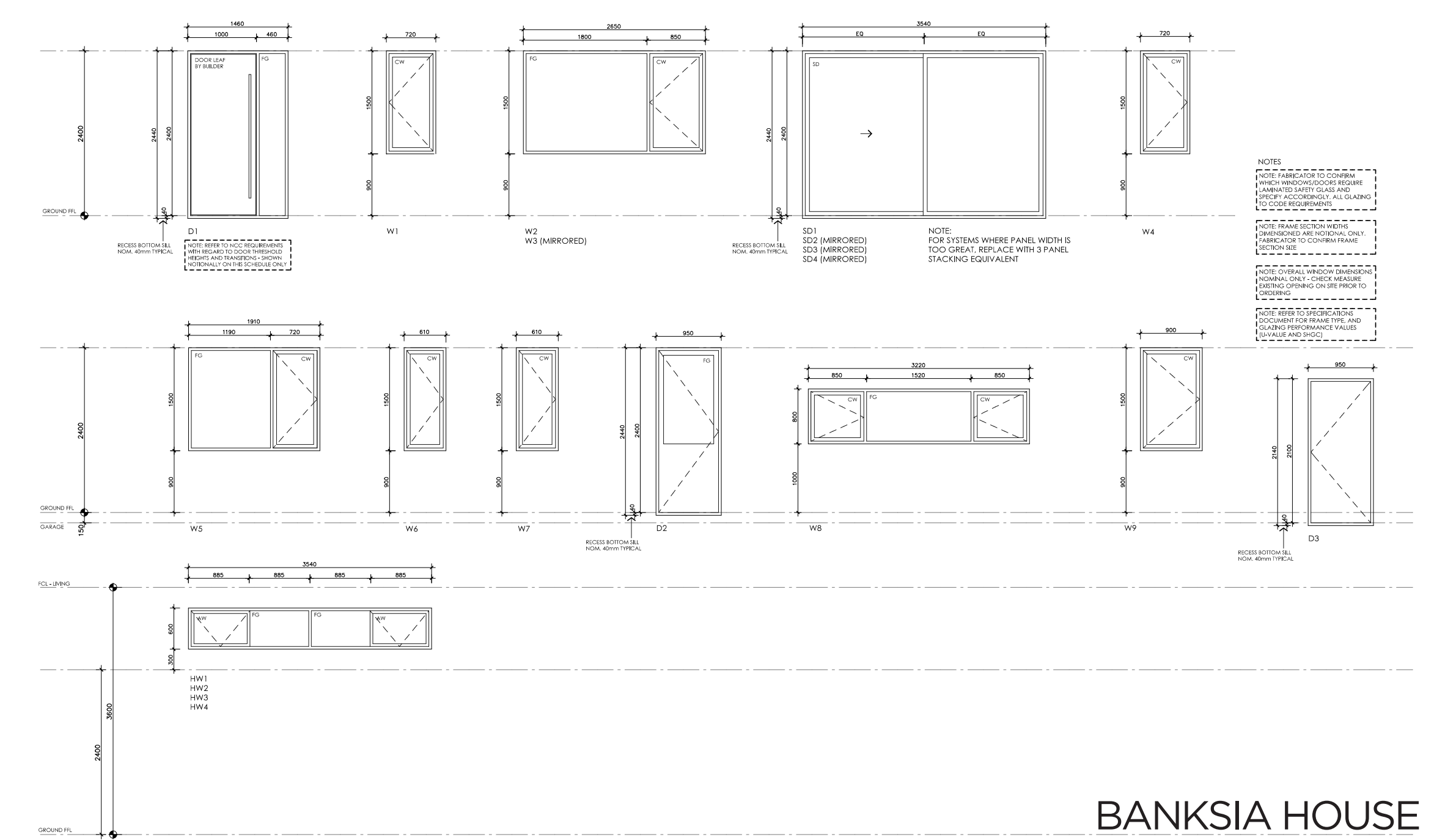
On the upper edge of Banksia's left bedrooms, locate window tags W2 and W3. The tags link these openings to the window and door schedule on sheet eleven. They do not themselves give the complete window dimensions or operating arrangement.
Banksia — Window and door schedule — sheet 11
A selected region of the Banksia window and door schedule, which the tags on the plan point to.
- Observe
- Find the row for the tag you carried across from the plan, then read along it to width, height and sill.
- Interpret
- A tag is a pointer; the schedule is where the item is actually described, which is why the two sheets have to be read together.
- Do not infer
- Do not read a schedule row as a location. The schedule cannot tell you which opening in the house it belongs to.
- Try next
- Carry W2 across and note what the schedule adds that the plan never showed.
What this sheet states about itself
- Pack
- Banksia (Brisbane)
- Sheet
- Sheet 11 of 11
- Drawing
- Window and door schedule, drawing 11/11
- Issue
- Preliminary issue, June 2023 — a preliminary house-design guide, not project-approved construction documentation.
- Scale
- The source sheet states 1:50 at A3 for the schedules. What is shown here is a selected screen extract of that sheet and is not to scale; do not measure it.
- Revision
- Revision not stated in the source. The supplied issue is Preliminary, June 2023.
Sources and limits for this figure
Actual Design For Place drawing extract.
© Commonwealth of Australia 2026. Design For Place, CC BY 4.0. Supplied free at Your Home. This extract is cropped from the source drawing; its remaining content has not been redrawn or corrected. Source logos and the Commonwealth Coat of Arms are excluded. No endorsement is represented.
Read this extract with the original source pack and the drawing companion. It is a preliminary example, not project-approved construction documentation. The screen image has no fixed drawing scale.
Source and rights:Banksia technical drawings
The Banksia technical drawings contain the principal June 2023 set followed by four older alternative sheets. The Telopea technical drawings contain twelve June 2023 sheets. Read them with the corresponding Banksia Design Options and Telopea Design Options.
The schedule presents W2 together with W3 as its mirrored counterpart. The drawn assembly has an overall width of 2,650 millimetres. The two parts are dimensioned 1,800 and 850 millimetres. In the schedule's legend, FG means fixed glass and CW means casement sash.
The dimension chain provides a useful check: 1,800 plus 850 equals 2,650. The tags and the mirrored note explain how one illustrated type can describe two differently handed arrangements. Mirroring changes which side contains the opening sash in the same illustrated view. The sash is the framed glazed part that opens. Mirroring should not be interpreted as changing the overall width or establishing an unstated inside-versus-outside viewing convention.
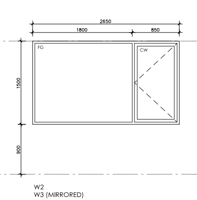
Banksia — W2 and mirrored W3 schedule extract — sheet 11
The W2 and mirrored W3 rows, cropped large enough to read.
- Observe
- Read the overall width, its division, the height and the sill height, then find the word that makes W3 different from W2.
- Interpret
- Mirroring swaps the handedness of an arrangement; it does not change the overall width, which is why both share one entry.
- Do not infer
- Read FG and CW using this sheet’s legend. Those opening descriptions do not establish glass composition, safety classification or thermal specification.
- Try next
- Add the sill height to the window height and check the head level the chapter states.
What this sheet states about itself
- Pack
- Banksia (Brisbane)
- Sheet
- Sheet 11 of 11
- Drawing
- Window and door schedule, drawing 11/11 (focused crop)
- Issue
- Preliminary issue, June 2023 — a preliminary house-design guide, not project-approved construction documentation.
- Scale
- The source sheet states 1:50 at A3 for the schedules. What is shown here is a selected screen extract of that sheet and is not to scale; do not measure it.
- Revision
- Revision not stated in the source. The supplied issue is Preliminary, June 2023.
Sources and limits for this figure
Actual Design For Place drawing extract.
© Commonwealth of Australia 2026. Design For Place, CC BY 4.0. Supplied free at Your Home. This extract is cropped from the source drawing; its remaining content has not been redrawn or corrected. Source logos and the Commonwealth Coat of Arms are excluded. No endorsement is represented.
Read this extract with the original source pack and the drawing companion. It is a preliminary example, not project-approved construction documentation. The screen image has no fixed drawing scale.
Source and rights:Banksia technical drawings
The Banksia technical drawings contain the principal June 2023 set followed by four older alternative sheets. The Telopea technical drawings contain twelve June 2023 sheets. Read them with the corresponding Banksia Design Options and Telopea Design Options.
The schedule also gives a window height of 1,500 millimetres and a sill relationship of 900 millimetres above the indicated floor datum. Adding those values gives a head at 2,400 millimetres in that illustrated relationship. That is a reading of this preliminary schedule, not a standard height for bedroom windows.
The schedule's notes qualify the dimensions and require fabricator and site checks. It also directs the reader to specifications for frame type and glazing performance. The small window elevation therefore answers some questions and points elsewhere for others.
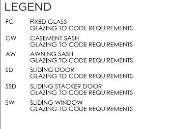
Banksia — Window schedule legend — sheet 11
The legend that defines the schedule's abbreviations on this sheet.
- Observe
- Find FG and CW in the legend and read the definitions the sheet itself gives.
- Interpret
- A legend is the sheet's own dictionary; using it is what stops a reader guessing a meaning from a symbol's shape.
- Do not infer
- Do not carry these definitions to another project's drawings without checking that project's legend.
- Try next
- Re-read the W2 row now that the abbreviations are defined.
What this sheet states about itself
- Pack
- Banksia (Brisbane)
- Sheet
- Sheet 11 of 11
- Drawing
- Window schedule legend, drawing 11/11 (focused crop)
- Issue
- Preliminary issue, June 2023 — a preliminary house-design guide, not project-approved construction documentation.
- Scale
- The source sheet states 1:50 at A3 for the schedules. What is shown here is a selected screen extract of that sheet and is not to scale; do not measure it.
- Revision
- Revision not stated in the source. The supplied issue is Preliminary, June 2023.
Sources and limits for this figure
Actual Design For Place drawing extract.
© Commonwealth of Australia 2026. Design For Place, CC BY 4.0. Supplied free at Your Home. This extract is cropped from the source drawing; its remaining content has not been redrawn or corrected. Source logos and the Commonwealth Coat of Arms are excluded. No endorsement is represented.
Read this extract with the original source pack and the drawing companion. It is a preliminary example, not project-approved construction documentation. The screen image has no fixed drawing scale.
Source and rights:Banksia technical drawings
The Banksia technical drawings contain the principal June 2023 set followed by four older alternative sheets. The Telopea technical drawings contain twelve June 2023 sheets. Read them with the corresponding Banksia Design Options and Telopea Design Options.
A different type, W1, is shown 720 millimetres wide and 1,500 millimetres high. Its similarity in height does not make it interchangeable with W2. Type identifiers preserve differences that a quick glance at a furnished plan might miss.
This route connects location, type, dimensions, operation and specification. It is more reliable than scaling the width of the window symbol from a reduced screen image. The printed scale applies at the stated paper size; a resized companion extract is for interpretation and must not be used as a construction scale.
The setout plan changes the emphasis
Banksia's setout plan is sheet ten. It describes the same principal house using denser dimensions and reference information. The furnished plan helps explain use. The setout plan helps locate construction. Neither is simply a more detailed version of every aspect of the other.
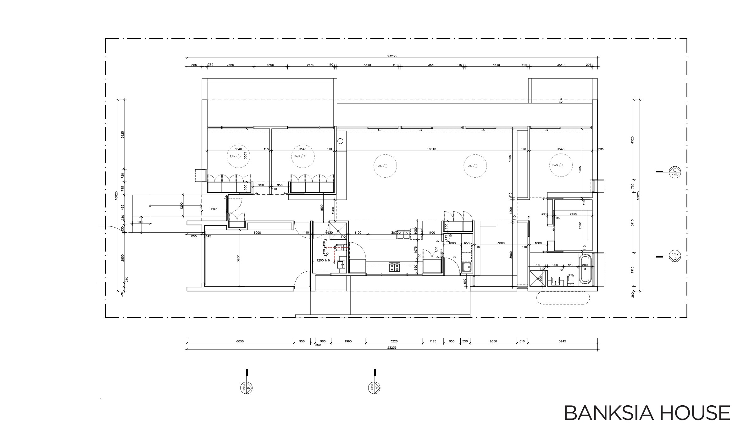
Banksia — Setout plan — sheet 10
The preliminary setout view emphasises dimensioned positions.
- Observe
- Compare this sheet with the floor plan: find what has been removed, and find the dimension strings that have been added.
- Interpret
- A setout plan changes the emphasis from arrangement to position, which is why it carries dimensions the furnished plan leaves out.
- Do not infer
- Do not scale a dimension from the screen, and do not assume a missing dimension is available elsewhere.
- Try next
- Pick one wall and say which sheet you would use to locate it on site.
What this sheet states about itself
- Pack
- Banksia (Brisbane)
- Sheet
- Sheet 10 of 11
- Drawing
- Setout plan, drawing 10/11
- Issue
- Preliminary issue, June 2023 — a preliminary house-design guide, not project-approved construction documentation.
- Scale
- The source sheet states 1:100 at A3. What is shown here is a selected screen extract of that sheet and is not to scale; do not measure it. Open the source pack to read its full dimensions, notes and scale instructions.
- Revision
- Revision not stated in the source. The supplied issue is Preliminary, June 2023.
Sources and limits for this figure
Actual Design For Place drawing extract.
© Commonwealth of Australia 2026. Design For Place, CC BY 4.0. Supplied free at Your Home. This extract is cropped from the source drawing; its remaining content has not been redrawn or corrected. Source logos and the Commonwealth Coat of Arms are excluded. No endorsement is represented.
Read this extract with the original source pack and the drawing companion. It is a preliminary example, not project-approved construction documentation. The screen image has no fixed drawing scale.
Source and rights:Banksia technical drawings
The Banksia technical drawings contain the principal June 2023 set followed by four older alternative sheets. The Telopea technical drawings contain twelve June 2023 sheets. Read them with the corresponding Banksia Design Options and Telopea Design Options.
An overall long dimension is printed as 23,235 millimetres. That establishes the distance between the particular endpoints of that dimension line. It does not mean every internal dimension chain should be added indiscriminately until it reaches that number.
A dimension chain may run between different faces from another chain. Wall thicknesses, internal clear spaces and external faces describe different intervals. Trace the extension lines to their endpoints before comparing totals. Arithmetic is useful only after the measured relationships are understood.
If a printed dimension and a scaled measurement seem inconsistent, first examine the issue, paper size, resizing and endpoints. A screen image can be stretched or reduced. A dimension can also contain a drafting error. The discrepancy is a reason to investigate, not permission to choose whichever value suits a preferred answer.
An elevation and a section reveal different things
Banksia's east elevation shows an exterior face. Its section sheets cut through the building. An elevation can show the external roof outline and openings while leaving the internal support and room relationship concealed. A section makes selected concealed relationships visible by cutting through them.
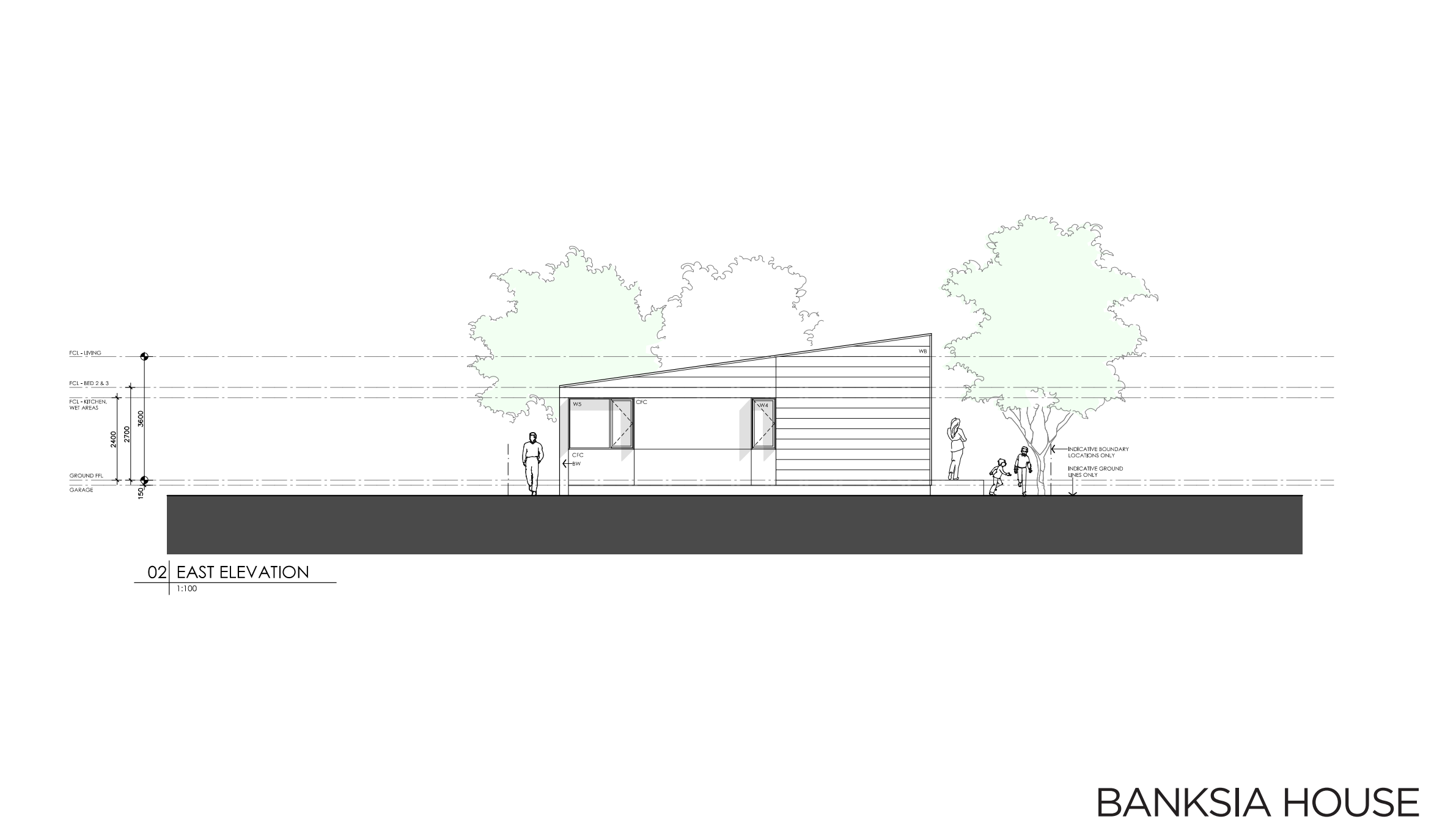
Banksia — East elevation — sheet 4
The east elevation: the same house seen from outside, straight on.
- Observe
- Find the openings you already know from the plan, and read their heights above the floor level line.
- Interpret
- An elevation answers vertical and appearance questions the plan cannot, using the same openings you have already located.
- Do not infer
- Do not read an elevation as a section — nothing here shows what is inside the wall.
- Try next
- Name one question about this house that the elevation still cannot answer.
What this sheet states about itself
- Pack
- Banksia (Brisbane)
- Sheet
- Sheet 4 of 11
- Drawing
- East elevation, drawing 4/11
- Issue
- Preliminary issue, June 2023 — a preliminary house-design guide, not project-approved construction documentation.
- Scale
- The source sheet states 1:100 at A3. What is shown here is a selected screen extract of that sheet and is not to scale; do not measure it. Open the source pack to read its full dimensions, notes and scale instructions.
- Revision
- Revision not stated in the source. The supplied issue is Preliminary, June 2023.
Sources and limits for this figure
Actual Design For Place drawing extract.
© Commonwealth of Australia 2026. Design For Place, CC BY 4.0. Supplied free at Your Home. This extract is cropped from the source drawing; its remaining content has not been redrawn or corrected. Source logos and the Commonwealth Coat of Arms are excluded. No endorsement is represented.
Read this extract with the original source pack and the drawing companion. It is a preliminary example, not project-approved construction documentation. The screen image has no fixed drawing scale.
Source and rights:Banksia technical drawings
The Banksia technical drawings contain the principal June 2023 set followed by four older alternative sheets. The Telopea technical drawings contain twelve June 2023 sheets. Read them with the corresponding Banksia Design Options and Telopea Design Options.
The section's heavy cut construction differs from thinner elements seen beyond the cut. Background trees and figures help communicate scale and setting; they are not survey measurements. The distinction between cut and background is essential when deciding which elements actually intersect the section plane.
Material notes on the sections describe the roof, wall and floor arrangement. Some refer structural framing, slab and footings to engineering details. The black graphic beneath a floor does not reveal reinforcement just because it looks substantial. Its note and reference establish the available level of information.
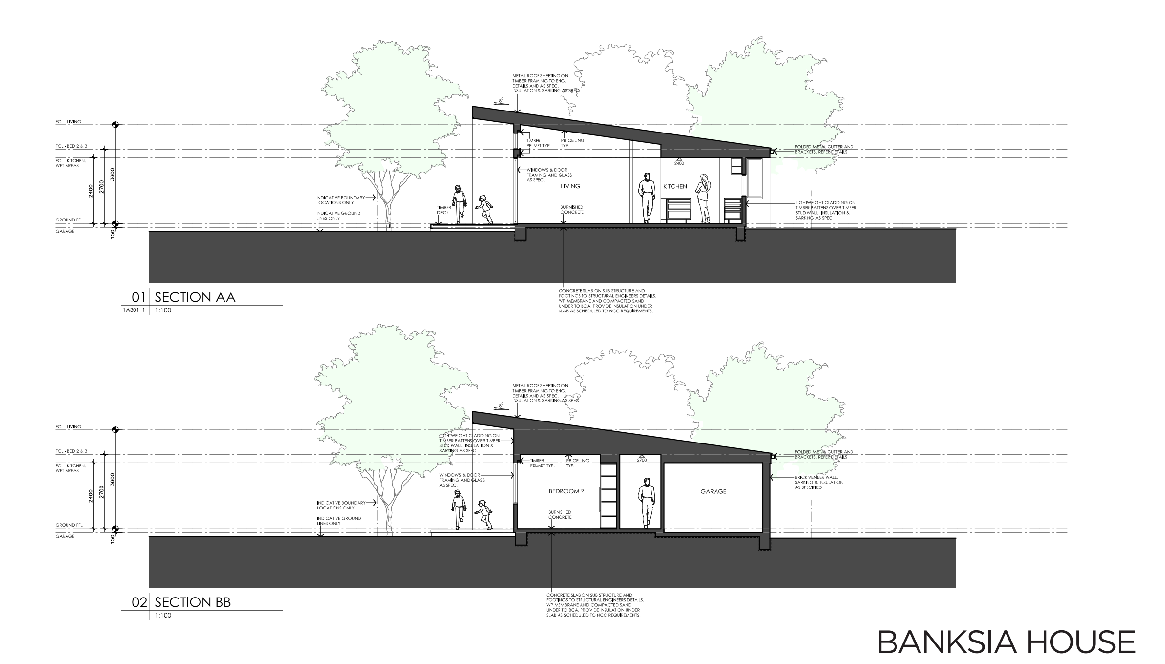
Banksia — Sections AA and BB — sheet 8
Two cuts through the same house, on one sheet.
- Observe
- Find each section's cut position on the floor plan first, then read the heights each cut reveals.
- Interpret
- A section is only readable once you know where it was taken and which way it looks.
- Do not infer
- Do not read the section as a construction detail, and do not assume the two cuts show the same rooms.
- Try next
- Predict what a third cut, through the entry, would show.
What this sheet states about itself
- Pack
- Banksia (Brisbane)
- Sheet
- Sheet 8 of 11
- Drawing
- Sections AA and BB, drawing 8/11
- Issue
- Preliminary issue, June 2023 — a preliminary house-design guide, not project-approved construction documentation.
- Scale
- The source sheet states 1:100 at A3. What is shown here is a selected screen extract of that sheet and is not to scale; do not measure it. Open the source pack to read its full dimensions, notes and scale instructions.
- Revision
- Revision not stated in the source. The supplied issue is Preliminary, June 2023.
Sources and limits for this figure
Actual Design For Place drawing extract.
© Commonwealth of Australia 2026. Design For Place, CC BY 4.0. Supplied free at Your Home. This extract is cropped from the source drawing; its remaining content has not been redrawn or corrected. Source logos and the Commonwealth Coat of Arms are excluded. No endorsement is represented.
Read this extract with the original source pack and the drawing companion. It is a preliminary example, not project-approved construction documentation. The screen image has no fixed drawing scale.
Source and rights:Banksia technical drawings
The Banksia technical drawings contain the principal June 2023 set followed by four older alternative sheets. The Telopea technical drawings contain twelve June 2023 sheets. Read them with the corresponding Banksia Design Options and Telopea Design Options.
A building section also differs from a junction detail. The section explains the larger relationship between spaces and construction. A detail enlarges a particular meeting point so its connections and layers can be resolved. The published Banksia pack does not contain every head, jamb, sill or structural connection detail.
Telopea: connect two floor plans
Telopea introduces a genuine two-storey arrangement. Its published pack contains twelve preliminary technical sheets. The ground-floor plan is sheet two; the upper-floor plan is sheet three. Each has its own room key and openings. The upper plan is not simply the lower plan repeated at another level.
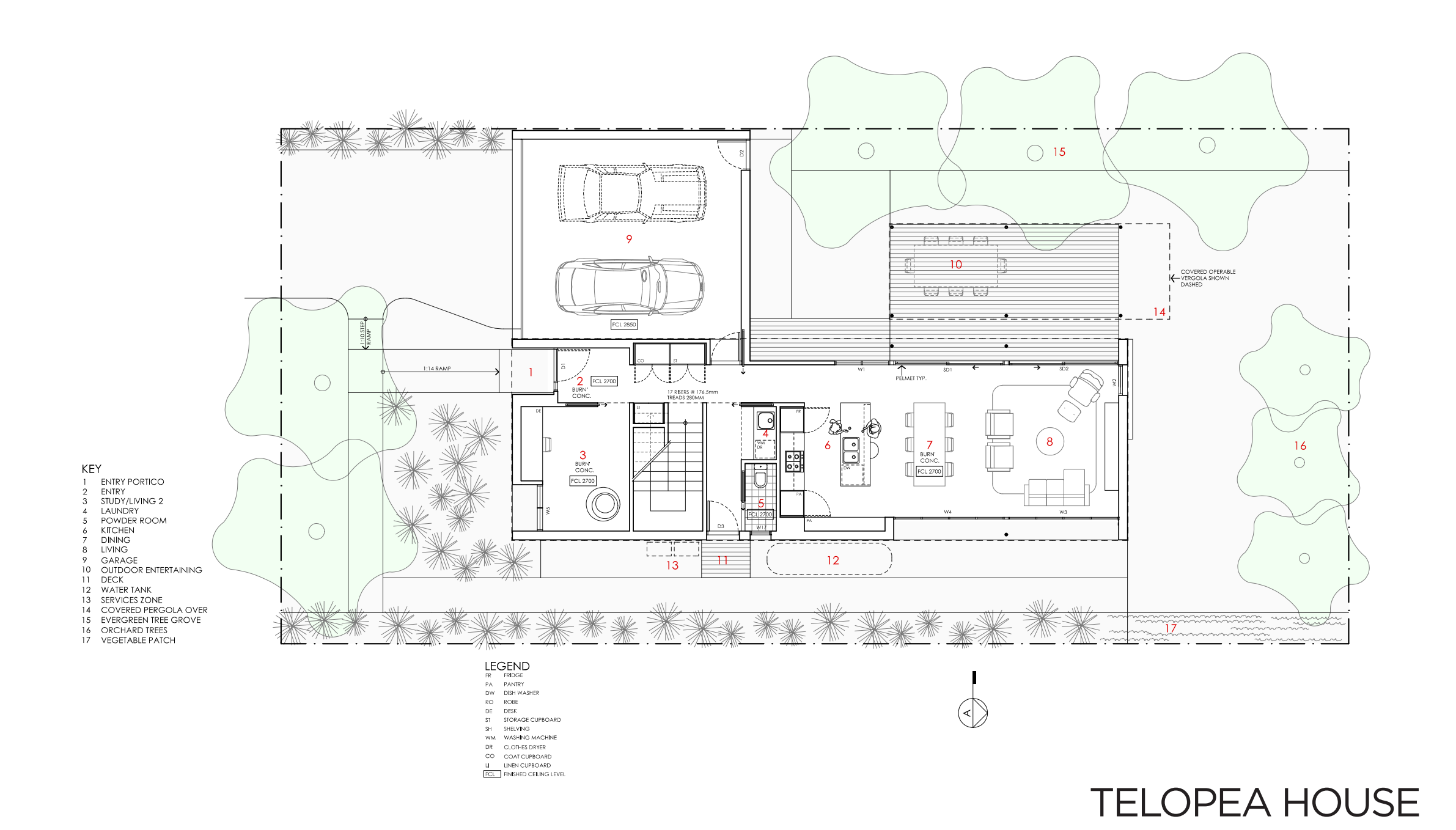
Telopea — Ground floor plan — sheet 2
The Telopea ground floor: a two-storey house starts here.
- Observe
- Find the stair, then the rooms it connects on this level.
- Interpret
- The stair is the reference that lets two floor plans be read as one house rather than two unrelated drawings.
- Do not infer
- Do not assume a room above sits over the room with the same name below.
- Try next
- Mark the stair before you open the upper plan.
What this sheet states about itself
- Pack
- Telopea (Brisbane)
- Sheet
- Sheet 2 of 12
- Drawing
- Ground floor plan, drawing 2/12
- Issue
- Preliminary issue, June 2023 — a preliminary house-design guide, not project-approved construction documentation.
- Scale
- The source sheet states 1:100 at A3. What is shown here is a selected screen extract of that sheet and is not to scale; do not measure it. Open the source pack to read its full dimensions, notes and scale instructions.
- Revision
- Revision not stated in the source. The supplied issue is Preliminary, June 2023.
Sources and limits for this figure
Actual Design For Place drawing extract.
© Commonwealth of Australia 2026. Design For Place, CC BY 4.0. Supplied free at Your Home. This extract is cropped from the source drawing; its remaining content has not been redrawn or corrected. Source logos and the Commonwealth Coat of Arms are excluded. No endorsement is represented.
Read this extract with the original source pack and the drawing companion. It is a preliminary example, not project-approved construction documentation. The screen image has no fixed drawing scale.
Source and rights:Telopea technical drawings
The Banksia technical drawings contain the principal June 2023 set followed by four older alternative sheets. The Telopea technical drawings contain twelve June 2023 sheets. Read them with the corresponding Banksia Design Options and Telopea Design Options.
The stair establishes a shared vertical route. On the upper plan, the landing and stair opening connect to circulation between bedrooms and bathrooms. Reading the upper plan alongside the ground plan helps explain where a person arrives and how the two levels relate.
Upper-floor windows carry a note about opening restrictions under the NCC. That note signals a fall-protection question for further resolution. It does not identify a verified hardware system by itself. The source remains preliminary, and the window schedule retains fabrication dependencies.
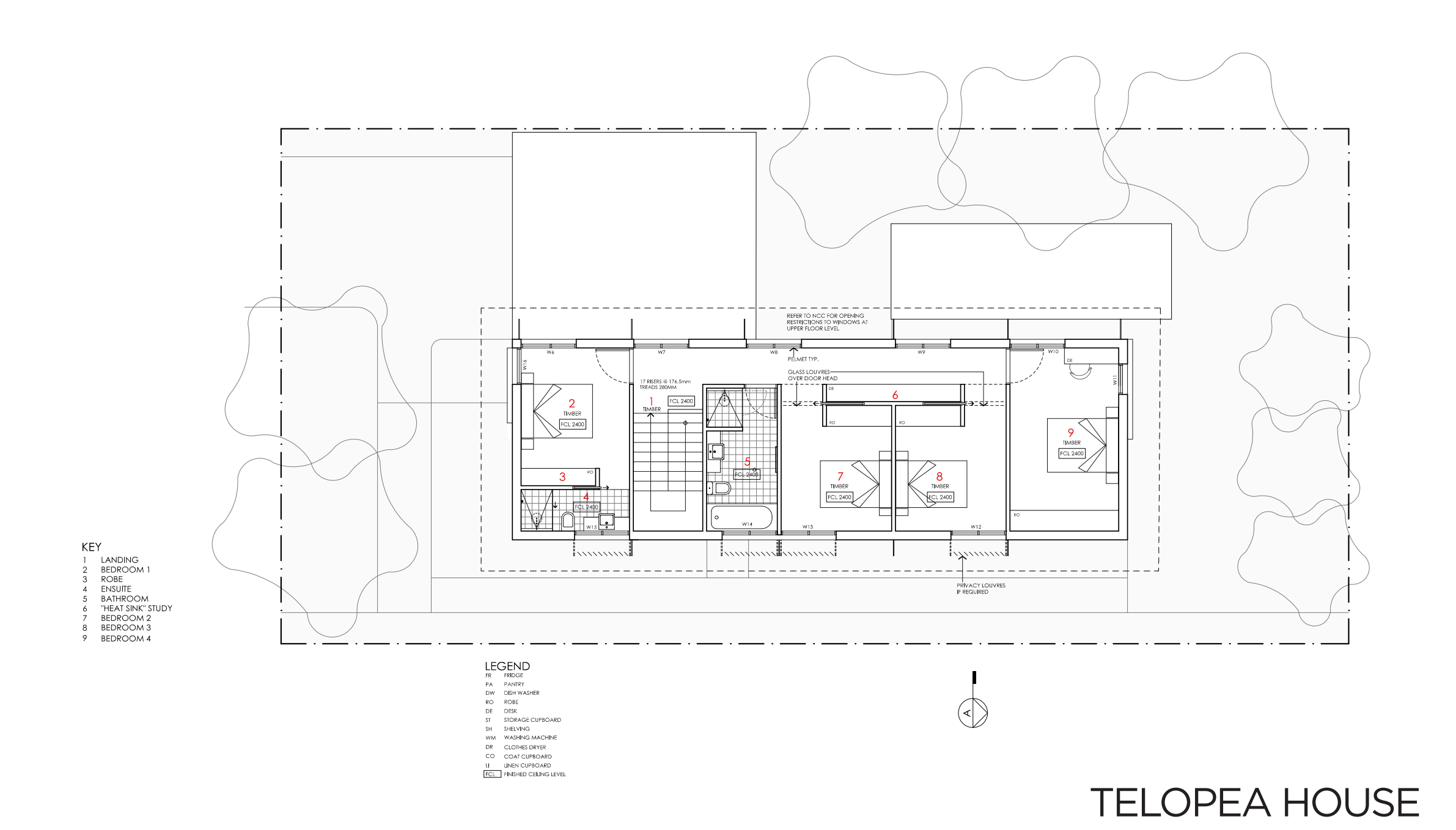
Telopea — Upper floor plan — sheet 3
The upper floor of the same house, aligned to the same stair.
- Observe
- Locate the stair again, then work outwards and compare the external wall positions with the floor below.
- Interpret
- Two plans become one building when a shared reference — here, the stair — is used to align them.
- Do not infer
- Do not infer floor-to-floor height from two plans. That is a vertical question for the section.
- Try next
- List which walls continue from the ground floor and which do not.
What this sheet states about itself
- Pack
- Telopea (Brisbane)
- Sheet
- Sheet 3 of 12
- Drawing
- Upper floor plan, drawing 3/12
- Issue
- Preliminary issue, June 2023 — a preliminary house-design guide, not project-approved construction documentation.
- Scale
- The source sheet states 1:100 at A3. What is shown here is a selected screen extract of that sheet and is not to scale; do not measure it. Open the source pack to read its full dimensions, notes and scale instructions.
- Revision
- Revision not stated in the source. The supplied issue is Preliminary, June 2023.
Sources and limits for this figure
Actual Design For Place drawing extract.
© Commonwealth of Australia 2026. Design For Place, CC BY 4.0. Supplied free at Your Home. This extract is cropped from the source drawing; its remaining content has not been redrawn or corrected. Source logos and the Commonwealth Coat of Arms are excluded. No endorsement is represented.
Read this extract with the original source pack and the drawing companion. It is a preliminary example, not project-approved construction documentation. The screen image has no fixed drawing scale.
Source and rights:Telopea technical drawings
The Banksia technical drawings contain the principal June 2023 set followed by four older alternative sheets. The Telopea technical drawings contain twelve June 2023 sheets. Read them with the corresponding Banksia Design Options and Telopea Design Options.
The two setout plans, sheets ten and eleven, both show an overall long dimension of 17,740 millimetres. Their common overall relationship helps compare the floors. It does not prove that every upper wall stands directly over a supporting wall below.
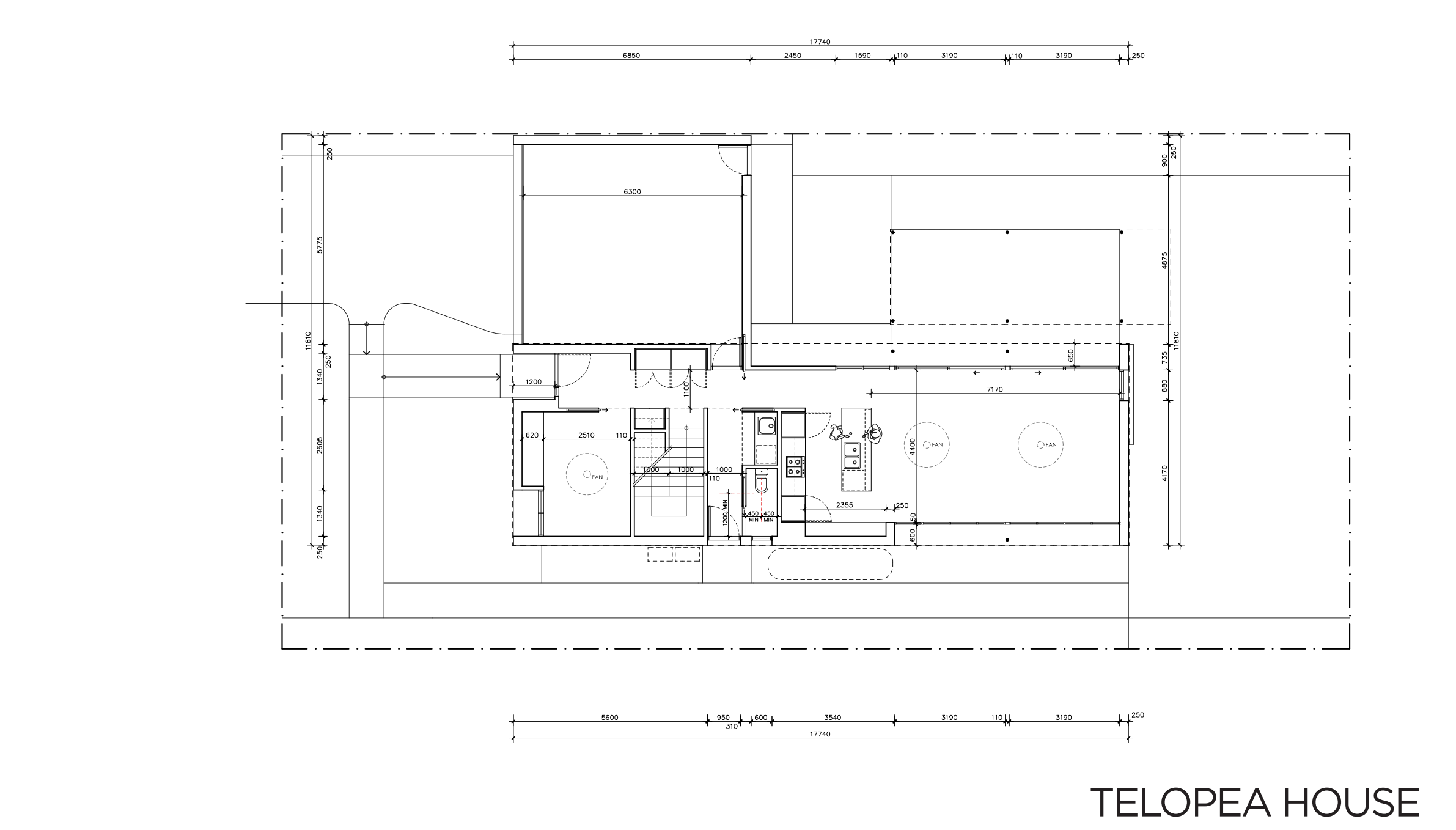
Telopea — Ground floor setout — sheet 10
The ground floor again, dimensioned for setting out.
- Observe
- Follow one dimension string from end to end and note what its endpoints actually are.
- Interpret
- A dimension is only usable when both its endpoints are identified; the setout sheet is where those endpoints are declared.
- Do not infer
- Do not add dimensions across sheets, and do not scale the screen image.
- Try next
- Find a dimension whose endpoints you cannot identify with certainty.
What this sheet states about itself
- Pack
- Telopea (Brisbane)
- Sheet
- Sheet 10 of 12
- Drawing
- Ground floor setout, drawing 10/12
- Issue
- Preliminary issue, June 2023 — a preliminary house-design guide, not project-approved construction documentation.
- Scale
- The source sheet states 1:100 at A3. What is shown here is a selected screen extract of that sheet and is not to scale; do not measure it. Open the source pack to read its full dimensions, notes and scale instructions.
- Revision
- Revision not stated in the source. The supplied issue is Preliminary, June 2023.
Sources and limits for this figure
Actual Design For Place drawing extract.
© Commonwealth of Australia 2026. Design For Place, CC BY 4.0. Supplied free at Your Home. This extract is cropped from the source drawing; its remaining content has not been redrawn or corrected. Source logos and the Commonwealth Coat of Arms are excluded. No endorsement is represented.
Read this extract with the original source pack and the drawing companion. It is a preliminary example, not project-approved construction documentation. The screen image has no fixed drawing scale.
Source and rights:Telopea technical drawings
The Banksia technical drawings contain the principal June 2023 set followed by four older alternative sheets. The Telopea technical drawings contain twelve June 2023 sheets. Read them with the corresponding Banksia Design Options and Telopea Design Options.
To investigate support, a reader needs the structural arrangement and relevant sections. An upper partition can be located over a floor that transfers its load elsewhere. Aligning two architectural plans is a starting point for that investigation, not the structural conclusion.
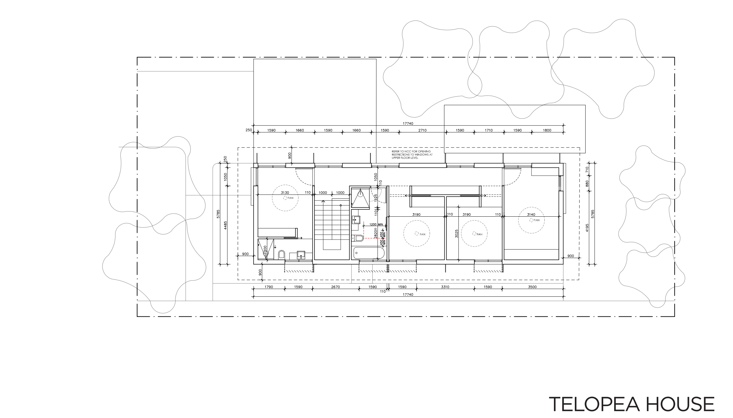
Telopea — Upper floor setout — sheet 11
The upper floor, dimensioned to match.
- Observe
- Compare a wall position here with the same wall on the ground floor setout.
- Interpret
- Vertical alignment between floors is a dimensioned relationship, not something to be judged by eye across two sheets.
- Do not infer
- Do not assume alignment because two plans look similar at reduced size.
- Try next
- Choose one wall and check whether it is actually above the one below.
What this sheet states about itself
- Pack
- Telopea (Brisbane)
- Sheet
- Sheet 11 of 12
- Drawing
- Upper floor setout, drawing 11/12
- Issue
- Preliminary issue, June 2023 — a preliminary house-design guide, not project-approved construction documentation.
- Scale
- The source sheet states 1:100 at A3. What is shown here is a selected screen extract of that sheet and is not to scale; do not measure it. Open the source pack to read its full dimensions, notes and scale instructions.
- Revision
- Revision not stated in the source. The supplied issue is Preliminary, June 2023.
Sources and limits for this figure
Actual Design For Place drawing extract.
© Commonwealth of Australia 2026. Design For Place, CC BY 4.0. Supplied free at Your Home. This extract is cropped from the source drawing; its remaining content has not been redrawn or corrected. Source logos and the Commonwealth Coat of Arms are excluded. No endorsement is represented.
Read this extract with the original source pack and the drawing companion. It is a preliminary example, not project-approved construction documentation. The screen image has no fixed drawing scale.
Source and rights:Telopea technical drawings
The Banksia technical drawings contain the principal June 2023 set followed by four older alternative sheets. The Telopea technical drawings contain twelve June 2023 sheets. Read them with the corresponding Banksia Design Options and Telopea Design Options.
The section answers one vertical question
Telopea's section AA is sheet nine. It shows a bedroom over the living space. The lower ceiling dimension is 2,700 millimetres and the upper is 2,400 millimetres. The section makes the stacked rooms and intervening floor zone visible.
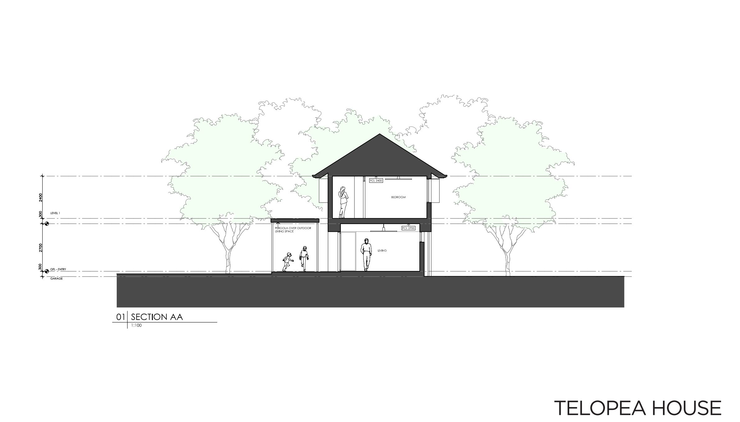
Telopea — Section AA — sheet 9
One vertical cut through the two-storey house.
- Observe
- Read the ceiling height on the lower level, then find the floor construction between the two levels.
- Interpret
- Room height and floor-to-floor height are different measurements, and the section is what separates them.
- Do not infer
- Do not take a 2700-millimetre ceiling height as the floor-to-floor height.
- Try next
- Work out what else would have to be added to reach the floor above.
What this sheet states about itself
- Pack
- Telopea (Brisbane)
- Sheet
- Sheet 9 of 12
- Drawing
- Section AA, drawing 9/12
- Issue
- Preliminary issue, June 2023 — a preliminary house-design guide, not project-approved construction documentation.
- Scale
- The source sheet states 1:100 at A3. What is shown here is a selected screen extract of that sheet and is not to scale; do not measure it. Open the source pack to read its full dimensions, notes and scale instructions.
- Revision
- Revision not stated in the source. The supplied issue is Preliminary, June 2023.
Sources and limits for this figure
Actual Design For Place drawing extract.
© Commonwealth of Australia 2026. Design For Place, CC BY 4.0. Supplied free at Your Home. This extract is cropped from the source drawing; its remaining content has not been redrawn or corrected. Source logos and the Commonwealth Coat of Arms are excluded. No endorsement is represented.
Read this extract with the original source pack and the drawing companion. It is a preliminary example, not project-approved construction documentation. The screen image has no fixed drawing scale.
Source and rights:Telopea technical drawings
The Banksia technical drawings contain the principal June 2023 set followed by four older alternative sheets. The Telopea technical drawings contain twelve June 2023 sheets. Read them with the corresponding Banksia Design Options and Telopea Design Options.
These ceiling dimensions are different from the complete floor-to-floor relationship. The floor assembly occupies space between the lower ceiling and the upper finished floor. A reader who adds only room heights omits the construction between them.
The section also shows an outdoor covered space beside the lower room. It helps explain how roof and floor levels relate across inside and outside. The dark ground and cut elements are graphic descriptions at this scale, not a site investigation or a detailed footing design.
One section cannot explain every part of a two-storey house. It does not pass through all wet areas, stair conditions or roof junctions. To answer a question about a location outside its cut, return to the plan and identify the additional view or detail required.
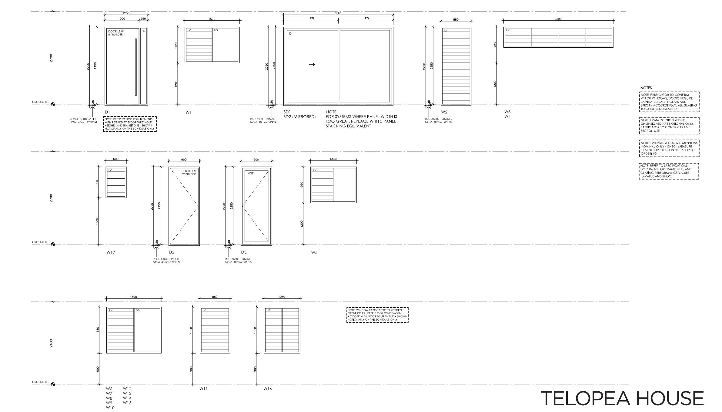
Telopea — Window and door schedule — sheet 12
The Telopea schedule, including the row that raises a real question.
- Observe
- Locate W6 on the upper plan, then compare its schedule datum label with the plan and section.
- Interpret
- A discrepancy between coordinated views and a datum label is a query to record, not a reason to silently change the source.
- Do not infer
- Do not silently rename the datum to make the sheet consistent. Record the query instead.
- Try next
- Write the question you would send to the drawing's author in one sentence.
What this sheet states about itself
- Pack
- Telopea (Brisbane)
- Sheet
- Sheet 12 of 12
- Drawing
- Window and door schedule, drawing 12/12
- Issue
- Preliminary issue, June 2023 — a preliminary house-design guide, not project-approved construction documentation.
- Scale
- The source sheet states 1:50 at A3 for the schedules. What is shown here is a selected screen extract of that sheet and is not to scale; do not measure it.
- Revision
- Revision not stated in the source. The supplied issue is Preliminary, June 2023.
Sources and limits for this figure
Actual Design For Place drawing extract.
© Commonwealth of Australia 2026. Design For Place, CC BY 4.0. Supplied free at Your Home. This extract is cropped from the source drawing; its remaining content has not been redrawn or corrected. Source logos and the Commonwealth Coat of Arms are excluded. No endorsement is represented.
Read this extract with the original source pack and the drawing companion. It is a preliminary example, not project-approved construction documentation. The screen image has no fixed drawing scale.
Source and rights:Telopea technical drawings
The Banksia technical drawings contain the principal June 2023 set followed by four older alternative sheets. The Telopea technical drawings contain twelve June 2023 sheets. Read them with the corresponding Banksia Design Options and Telopea Design Options.
The window schedule contains a further reading caution: a generic ground-floor datum label appears beneath upper-window types. Reading that wording alone would place them incorrectly. The upper plan, elevation and section establish that the openings belong upstairs. The preliminary schedule's presentation needs clarification rather than an invented explanation of why an upper window is at ground level.
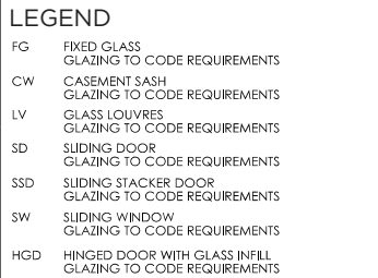
Telopea — Window schedule legend — sheet 12
The Telopea sheet's own definitions for its schedule abbreviations.
- Observe
- Read the legend before interpreting any row of the schedule beside it.
- Interpret
- Each pack defines its own abbreviations; the legend is the only authority for what they mean on this sheet.
- Do not infer
- Do not assume this legend matches the Banksia legend without comparing them.
- Try next
- Compare the two legends and note any difference.
What this sheet states about itself
- Pack
- Telopea (Brisbane)
- Sheet
- Sheet 12 of 12
- Drawing
- Window schedule legend, drawing 12/12 (focused crop)
- Issue
- Preliminary issue, June 2023 — a preliminary house-design guide, not project-approved construction documentation.
- Scale
- The source sheet states 1:50 at A3 for the schedules. What is shown here is a selected screen extract of that sheet and is not to scale; do not measure it.
- Revision
- Revision not stated in the source. The supplied issue is Preliminary, June 2023.
Sources and limits for this figure
Actual Design For Place drawing extract.
© Commonwealth of Australia 2026. Design For Place, CC BY 4.0. Supplied free at Your Home. This extract is cropped from the source drawing; its remaining content has not been redrawn or corrected. Source logos and the Commonwealth Coat of Arms are excluded. No endorsement is represented.
Read this extract with the original source pack and the drawing companion. It is a preliminary example, not project-approved construction documentation. The screen image has no fixed drawing scale.
Source and rights:Telopea technical drawings
The Banksia technical drawings contain the principal June 2023 set followed by four older alternative sheets. The Telopea technical drawings contain twelve June 2023 sheets. Read them with the corresponding Banksia Design Options and Telopea Design Options.
Specifications describe selected combinations
Design For Place provides Design Options documents alongside the technical sheets. These compare material and equipment arrangements with stated modelling assumptions. They must be read as combinations within the particular design and location.
Selecting a glazing option from one column and insulation from another changes the combination. The resulting proposal cannot inherit a modelled outcome from either original column without further analysis. A rating relates to its inputs, not to a collection of individually attractive products.
The options identify materials and equipment without supplying complete structural or services designs. A reference to an upper timber floor does not provide joist sizes and connections. A heating-system option does not draw ducts and condensate routes. A roof plan showing gutters does not establish hydraulic capacity or the legal discharge point.
This is a productive boundary for a learner to recognise. The documents are useful precisely because they communicate considerable architectural information while exposing dependencies. Reading well means understanding both what is present and what remains to be supplied.
Compare disciplines through a shared reference
A separate public school example shows how consultant drawings can be compared. The Dundas Public School project in New South Wales published structural, mechanical and hydraulic drawings at different design stages. Its consultant report describes the proposal as Class 9b, Type C under the 2022 Building Code of Australia, abbreviated to BCA. It is a labelled non-residential example; the house-design methods in this book do not automatically become its regulatory pathway.
The structural and mechanical plans use common grids A to G and one to three around the same long building footprint. A grid provides a shared location reference across disciplines. It allows a reader to describe a bay without relying on a room name that may change.
Common grids do not prove coordination. Dates, revisions and drawing stages must also be checked. The structural material is schematic design, and the mechanical sheets retain unresolved location and coordination notes. The project's later completion date does not convert those earlier public drawings into as-built records.
On the mechanical ground-floor plan, a keyed note links toilet exhaust to a roof cowl. The roof plan locates the corresponding item within the same grid system. That is a real example of following a service from one view to another.
The structural roof sheet refers relevant penetration information to the mechanical drawings, while the main roof framing is supplied by others. The pair therefore reveals the next coordination question: how will the opening and service support be resolved within the actual roof framing? It does not supply the missing connection merely because both sheets mention the penetration.
This reading method transfers back to a house project. Locate the service, follow it through the relevant views, compare the structure and identify the unresolved interface. The school example demonstrates that method without becoming a residential construction detail.
A register can reveal an absent sheet
The public hydraulic subset for the same school lists five drawings but contains four. Its legend and general-notes sheet is missing. Its details sheet is present. That distinction matters because the absence of a legend can limit decoding even when a useful detail remains available.
The cover and details have a different revision letter from the site sheets, despite sharing a tender date. A set does not always have one revision applying identically to every sheet. The register and individual titleblocks must be compared.
The details include plan and section views and indicate flow direction. Their not-to-scale designation prevents extracting dimensions by ruler. Their tender and not-for-construction status limits their use. A clear view can teach how information is represented without authorising installation from that view.
The source links in the companion lead to these publicly inspectable consultant documents. Their copyright remains with the relevant rights holders. The Fieldbook's explanations identify reading relationships; they do not reproduce or certify the proprietary project details.
Turn a discrepancy into a useful question
Imagine that an architectural ceiling line and a mechanical service route appear to occupy the same space. A useful query identifies the location, drawing numbers, revisions and the physical conflict. It asks which arrangement is to be revised and what related documents need updating.
“Please check services” is too broad to preserve the reasoning. “The proposed duct crosses the beam zone in this section; confirm a coordinated route and finished ceiling level” describes a specific relationship. The supporting markup should use the actual current drawings and retain enough context to locate the issue.
The response must then be recorded in the appropriate design and issue process. An email explanation alone may not update the drawing used by the next person. The agreed change needs to reach every affected description of the building.
Reading a set is therefore an active process of connecting evidence. Begin with issue identity, understand the overall arrangement, follow references and compare related views. Use dimensions for the relationships they actually measure. Recognise when a note delegates information elsewhere. A coordinated design emerges through those connections; a folder of drawings is only the place where the investigation begins.