
A Building Is a Team's Work
Follow a changed window through a design team’s responsibilities, communication, project sequence, records and safe design decisions.
The opening that moved
A client asks for a wider window. On a screen, the change looks small. Two lines move apart and a dimension increases. In the building, that opening belongs to a wall, a room, an elevation and several systems. Changing it may affect much more than the view.
Move one line. Let the light spread.
An optional 3D room for this figure
The plan, the elevation and the explanations below work without it.About this illustration Source, meaning and limits ↗
Original fictional teaching scene for Chapter 1, “The opening that moved”. This variation develops Figure V21 using one control to compare a small central opening, a taller opening and a wider divided-window arrangement. These are illustrative design alternatives, not a historical sequence or a construction method. The original V21 fixed-left-edge diagram, disclosed below this study, remains unchanged. No dimension, product, support or approval is specified. This original model is not a measured reconstruction and does not establish the location, date or classification of a building. Furnishings and planting establish visual context only.
The lighting is illustrative: a fixed directional light and simple materials demonstrate a changing shadow footprint. This is not a daylight, solar-access, energy, glare or structural simulation. No performance conclusion should be drawn from it, and nothing here is engineering advice.
Orange follows the changing right edge in the drawings; the dashed elevation outline marks the earlier opening. Labels and line styles carry the meaning as well as colour. Written explanations and linked drawings remain available without the 3D scene. Open the original Figure V21 diagram ↗
View original Figure V21 — plan and elevation
One changed opening, in plan and in elevation
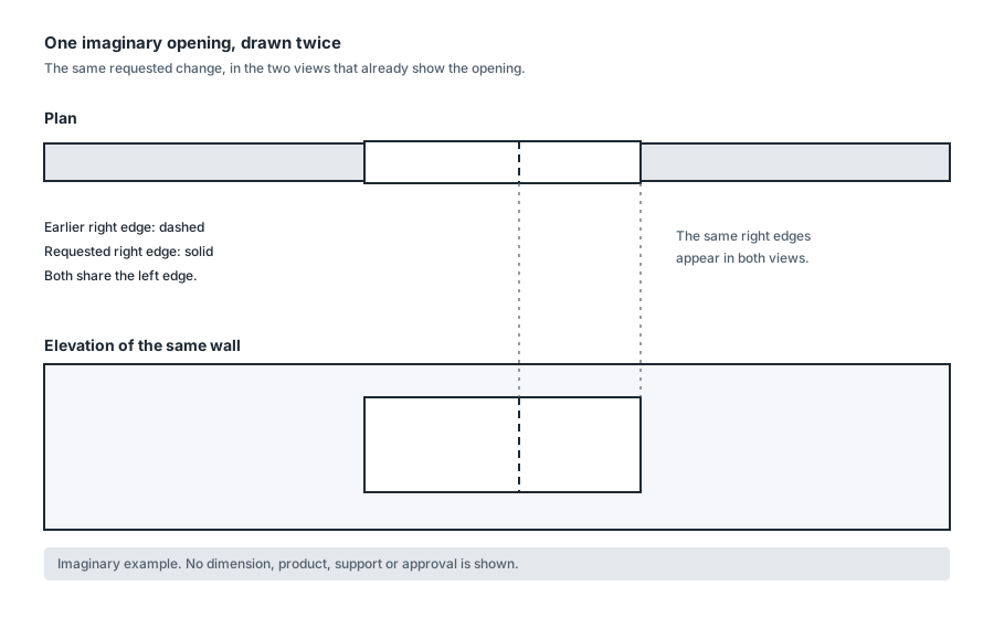
The requested change itself: one opening, drawn once in plan and once in elevation.
- Observe
- Find the dashed earlier right edge and solid requested right edge in each view. Follow their projection links; the left edge stays in place.
- Interpret
- A change to one opening appears in every view that already shows it, which is why a drafter identifies the affected views before redrawing anything.
- Do not infer
- Do not read any dimension, product, support or approval from this figure. No size is shown, and nothing here is decided.
- Try next
- Open a drawing set you have and list the views that would need redrawing after the same request.
Sources and limits for this figure
Original fictional teaching diagram created for this Fieldbook.
The upper view is a plan of one wall, drawn as a band. The lower view shows the same wall in elevation. A solid outline shows the wider requested opening. A dashed vertical line inside it marks the earlier right edge; the left edge stays in place.
Thin projection links connect the earlier and requested right edges at matching horizontal positions in both views. The earlier edge remains visible instead of being covered by the wider outline. This makes the effect of one requested change visible across two drawings.
The line styles are local teaching conventions. Nothing is dimensioned; no lintel, product, fixing, material or approval is represented.
Original fictional teaching diagram created for this Fieldbook; not a surveyed or construction document.
Source and rights:Original fictional teaching diagram
Created for this Fieldbook from chapter 1, 'The opening that moved'. No dimension, product or approval is shown.
Something above the opening needs support. The window needs to resist weather and operate as intended. Its size and position may affect privacy, daylight, heat gain or a nearby fixture. Other drawings may still show the earlier opening. A small drafting change can therefore become a coordination problem.
This is where building design begins to look different from drawing an attractive picture. A design describes a proposed physical environment that people will construct, use, maintain and eventually alter. The information must make sense across those purposes and across the people contributing to it.
One changed opening and the work it reaches
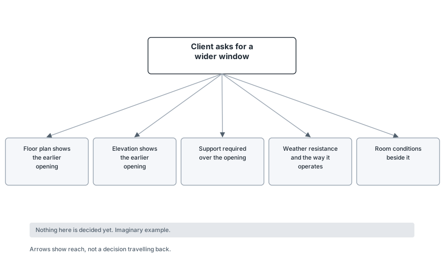
One requested change, and the separate roles it reaches before anyone decides anything.
- Observe
- Follow the arrows from the wider opening out to each labelled role: the plan, the elevation, the support above, weathering and operation, and the room conditions beside it.
- Interpret
- A change that looks like two moved lines belongs to several people's work at once, which is why a drafter identifies the affected views before redrawing them.
- Do not infer
- Do not read this as a structural solution, an approved instruction or a complete list of everyone a real project would involve.
- Try next
- Name one more view or record in your own project that would need checking after the same request.
Sources and limits for this figure
Original fictional teaching diagram created for this Fieldbook.
The centre of the figure holds the request: a client asks for a wider window. Five arrows leave it. Two reach drawings that already show the earlier opening — the floor plan and the elevation. One reaches the support required over the opening. One reaches weather resistance and the way the window operates. One reaches the room conditions beside it: privacy, daylight, heat gain and any nearby fixture.
The arrows point outward only. They record that a change reaches these roles; they do not show a decision travelling back. A band across the foot of the figure states that nothing here has been decided, authorised or resolved.
No dimension, structural member or product is shown, because the passage this figure accompanies deliberately stops before those choices are made. The project is imaginary and the roles are the ones named in the chapter, not a complete list of everyone a real project involves.
Original fictional teaching diagram — created for this Fieldbook. Its conventions are stated locally; it is not a surveyed or construction document.
Source and rights:Original fictional teaching diagram
Created for this Fieldbook from chapter 1, 'The opening that moved'. Diagram conventions are stated locally; this is not a surveyed or construction document.
For a beginning drafter, the immediate responsibility is to understand the task, its source and its limits. A request to draw a wider opening is not automatically an instruction to choose its structural support. Nor is the ability to edit a drawing evidence that the proposed change has been authorised.
A careful drafter can still make an important contribution before those questions are settled. They can identify the affected views, locate the current information and describe what requires a decision. Supporting the designer includes making the consequences of a change visible.
The examples in this book use imaginary projects unless a real building or source is named. Their purpose is to explain relationships and professional reasoning. They are not instructions for constructing a particular building or a substitute for supervised practice.
Different kinds of responsibility
A client brings needs, priorities and constraints to a project. These may include space, cost, time, appearance and the way the building will be used. A brief records those requirements in a form that can be discussed and developed. It rarely answers every technical question at the outset.
A building designer or architect develops and coordinates the design within their appointment and professional responsibilities. The exact scope varies between projects. A title alone does not establish that one person has been engaged to perform every design, approval and construction function.
A drafter prepares and manages information supporting that work. Drafting can involve producing drawings, incorporating authorised changes, comparing documents and identifying inconsistencies. It also involves recording where information came from and preserving it so that others can use it reliably.
Supervision does not make drafting mechanical. A line can carry a technical implication even when the drafter did not originate the design decision. Recognising an unclear instruction and seeking appropriate advice is part of useful professional judgment.
External consultants contribute specialised information. A land surveyor may supply a survey within an agreed scope. A structural engineer may develop structural design information. Other specialists may address building services, geotechnical conditions, energy performance, access, planning or particular environmental risks.
Their roles can overlap at an interface without becoming interchangeable. A structural drawing may identify support around a window. The architectural documents still need to coordinate the opening's location and intended appearance. A services requirement may affect space within a ceiling, while the ceiling's height remains important to the room below.
Builders and trade contractors contribute knowledge about construction, sequencing, access and installation. Manufacturers provide information about their products and systems. Their advice needs to be understood in context: what exactly was considered, under which conditions, and with what responsibility for the resulting design?
Permit and approval authorities perform roles established by the relevant system. Their names and arrangements differ between jurisdictions. A planning decision, a building approval and a consultant's design review answer different questions. One should not be casually described as completing the others.
At the start of a task, it helps to identify who supplies information, who coordinates it and who decides the unresolved issue. This is more useful than assuming that every message from a consultant is an instruction the drafter may implement immediately. Project procedures and the supervising designer establish the authorised route.
A sequence with feedback
Design work usually begins by clarifying what is wanted and what is already known. Site information, the intended use, available resources and relevant controls shape the early possibilities. A preliminary arrangement then gives the team something concrete to examine.
As the design develops, questions become more specific. A room arrangement creates openings and circulation routes. Those choices interact with structure, services, environmental performance and construction methods. Information from specialists can require the arrangement to change again.
Documentation describes the developed proposal at the level required for its purpose. Early discussion drawings do not necessarily contain the detail expected in later construction information. A drawing's intended use therefore matters as much as the skill with which it has been produced.
This sequence is not a straight road on which every question stays behind once answered. A later investigation can reveal a constraint that affects an earlier choice. Good information management allows the team to understand the change and its consequences without losing the history of the decision.
Consider our wider window. At an early stage, several widths may be explored as alternatives. Later, one width may have been coordinated with structure and included in an issued set. Changing it then has different consequences, because more information and decisions now depend on it.
A useful instruction identifies that context. “Explore a wider opening for discussion” differs from “update the coordinated opening to the approved dimension”. Both involve drawing work. Only the second describes an authorised design change, and even then the relevant affected documents need to be identified.
The drafter should not quietly transform a discussion option into issued information. A clear status separates a possibility from the proposal currently being relied on. That distinction protects the usefulness of early exploration as well as the reliability of later documentation.
Time is connected to information
A drawing task can take an hour of concentrated work and still require several days to complete. The missing time may be waiting for a consultant's response, a client decision or a current survey. Duration includes dependencies, not just keyboard activity.
Suppose a drawing issue is planned for Friday. The revised structural information is expected on Thursday afternoon. The drafter still needs time to incorporate it, check affected views and allow the responsible reviewer to inspect the changes. Receiving the information does not mean the drawing is immediately suitable for issue.
A realistic programme recognises those steps. It identifies what must arrive first and what can proceed independently. It also leaves an appropriate allowance for uncertainty. This allowance is contingency: time or another resource reserved for developments that cannot be predicted exactly.
Contingency is not an invitation to leave every decision late. It acknowledges that investigations and coordination sometimes reveal new work. Making the allowance visible is more honest than hiding it within optimistic estimates and hoping that no problem occurs.
When a dependency threatens the programme, describe the effect early. The relevant message is not merely that someone has failed to reply. It is that a particular decision is outstanding and a particular drawing or review depends on it. That information helps the team choose what can continue and what must wait.
A calendar can reserve a review meeting and show when information is needed. A task list can identify responsibility and progress. Neither tool resolves a technical dependency on its own. The value comes from keeping the recorded sequence connected to the actual work.
Communication that preserves meaning
Effective communication begins with the recipient's question. A client may need to understand how a changed opening affects the room. A structural consultant may need dimensions, locations and the relevant drawing issue. The same project fact can require different explanations for different readers.
Technical vocabulary is useful when it makes meaning more precise. It becomes a barrier when an unfamiliar word is left unexplained. A drafter communicating with a non-specialist can introduce the term and explain what it describes, rather than replacing it with a vague phrase.
For example, the window's head is the top of the opening. Once that meaning is established, “head height” is a compact way to discuss its vertical position. Calling it “the upper bit” may sound simpler but makes a technical exchange less precise.
Written communication should make the purpose evident early. Is the message supplying information, requesting clarification or recording a decision? Mixing those purposes can leave the recipient unsure whether a response or an action is expected.
Imagine a message that says, “The window has changed; please check.” It leaves several questions unanswered. Which window, on which drawing and revision? What changed? Which aspect needs checking? When is the response needed, and which work depends on it?
A more useful account identifies the opening and the proposed change, links the relevant issue and names the question. It might explain that the width increased while the sill height remained the same. The structural consultant can then identify the support question without guessing which marks on an attachment matter.
This is not a reason to make every email long. Clear identifiers and one well-defined question can shorten an exchange. The aim is enough context to prevent avoidable misunderstanding, with supporting detail located where the recipient can retrieve it.
Spoken discussions need the same care. Before concluding that an instruction is understood, restate the part that affects the work. If two people use “left” while looking from opposite directions, they may agree verbally while imagining different locations. A drawing reference or named viewpoint can resolve that ambiguity.
A meeting leaves a record
A useful meeting record preserves decisions and the work that follows from them. It does not need to reproduce every sentence spoken. It should distinguish a decision from an option discussed, and an agreed action from an unresolved question.
Suppose the team discusses enlarging the window but asks for a revised cost before deciding. A note stating “window to be enlarged” misrepresents the outcome. The team has agreed to investigate a change, not necessarily to implement it.
The record can identify the proposed option, who will obtain the information and when the decision will return for consideration. Later readers can then understand why the drawing remains unchanged. Without that context, the absence of a change may look like an oversight.
Record the meeting's identity, date and relevant participants so that its context can be recovered. Link decisions to the project information they affect. Where a person's agreement or responsibility is unclear, seek clarification through the agreed process rather than writing certainty into the minutes.
Meeting notes become part of the information system. They need a retrievable location and an identifiable version. An accurate record kept only in someone's private notebook may be unavailable when another person needs to understand the decision.
Quality begins before checking
Checking is essential, but quality is not created only at the end of a task. An unclear instruction can produce a neatly drawn error. An outdated source can lead to consistent drawings that describe the wrong proposal. Preventing those problems begins before the first line changes.
Establish the current source and the task's intended outcome. Keep changes identifiable while working. Compare related information after the change. Submit it through the required review and issue process. These steps support one another because each preserves something the next person needs.
A check also needs a defined purpose. Visual alignment, arithmetic, document coordination and technical design review are different activities. A tidy sheet may pass a presentation check while retaining an unresolved design issue. The record should say what was checked, not merely that someone checked it.
Errors should be communicated in a way that helps correction. Identify the location, describe the discrepancy and explain its consequence where known. Avoid disguising uncertainty as a confident diagnosis. “These two dimensions disagree” is different from “the structural drawing is wrong”.
This distinction matters in a team. A precise observation can be useful even when the drafter cannot determine the correct technical resolution. It gives the responsible person a question supported by evidence rather than an unsupported accusation.
Safety belongs to the work
The design office is a workplace as well as a place where buildings are imagined. Workstation arrangement, prolonged static work, electrical equipment, clutter and workload can affect people's health and safety. Appropriate workplace procedures apply to the actual conditions, including work away from the main office.
Useful habits connect the work to its physical setting. A screen should be readable without an awkward sustained posture. Equipment and cables should not create avoidable obstructions. A task requiring prolonged concentration needs a workable arrangement of activity and breaks. Specific adjustments should follow the workplace's guidance and individual needs.
Site visits introduce different conditions. Traffic, uneven ground, weather, existing structures and ongoing work can change what an inspection safely involves. Office familiarity with a drawing does not establish that a site is safe to enter. Planning a visit includes confirming access, conditions and the required site arrangements.
Safety also belongs to the design itself. A proposed feature will be constructed and later used, cleaned, maintained or replaced. A choice that appears convenient in a drawing can create difficulty during one of those stages. Safe design asks about those foreseeable activities while changes are still possible.
For a drafter, a useful contribution is to identify and communicate the relevant condition. A high inaccessible surface may prompt a maintenance question. A component requiring replacement may need an access route. Recognising the question does not authorise the drafter to invent a complete technical solution.
Design responsibility, workplace responsibility and approval processes must remain distinguishable. Following an office procedure does not establish that the building design satisfies every applicable requirement. Likewise, an approved drawing does not remove the need to manage the actual conditions encountered during construction.
Design choices and duty of care
Duty of care describes responsibility towards people who may be affected by work and decisions. In building design, concern for the intended user sits alongside concern for others who construct, maintain or alter the building. It is broader than satisfying a client's preference for an appearance.
Safe Work Australia's model guidance on safe design explains duties within the model work health and safety framework. The applicable jurisdiction's law must still be checked. The model guidance is useful for understanding how design decisions can create, reduce or pass on risks through a structure's life.
A design duty can depend on the influence a person actually exercises, rather than their job title alone. Specifications, instructions and modifications can affect safety as well as original drawings. A drafter should therefore understand the consequences of their work and the limits of the decisions they are authorised to make.
Consider a proposed external fitting that requires regular maintenance high above uneven ground. Recording “maintenance access required” identifies a concern, but it has not yet addressed the risk. Someone will still need to reach the fitting, use equipment and work in that setting.
The team can first consider whether the need for that hazardous task can be removed. Could the design locate the serviceable part where it can be reached from an appropriate level? Could a different arrangement avoid the repeated high-level activity? Those options change the source of exposure rather than merely warning the future worker.
If the task cannot be eliminated, the team considers suitable ways to reduce the remaining risk. A designed access arrangement or other engineering measure may be relevant. Its suitability requires the appropriate expertise and consideration of how it will be used. A note recommending protective equipment is not equivalent to resolving the access problem.
This illustrates the hierarchy of controls: eliminating a hazard comes first, followed by approaches that reduce exposure more directly. Administrative measures and personal protective equipment generally depend more heavily on people's actions. They may still form part of a solution, but should not automatically replace feasible design improvements.
Choosing a control also requires considering consequences elsewhere. Moving equipment may reduce a maintenance risk while creating a new access, structural or services issue. Consultation helps the team test the option against the people and systems affected. The decision needs more than a favourable appearance on one drawing.
The model framework's concept of reasonably practicable action includes the likelihood and severity of harm, available knowledge and suitable controls. Cost is considered in that context. It is not a simple instruction to choose the cheapest option that sounds acceptable.
The drafter's record can make this reasoning retrievable. It identifies the original concern, the authorised design response and any remaining conditions that others need to know. Passing on information supports safety, but does not magically transfer every responsibility away from the person who made a design decision.
Quality, intended purpose and applicable requirements remain connected here. A component may look correct while being difficult to maintain safely. A beautifully coordinated drawing may still describe an unsuitable choice. Care in design involves asking whether the information and the physical proposal serve the people and purposes they will affect.
Working with information others can trust
Return once more to the opening that moved. The useful result is more than a wider rectangle. It is a coordinated change with an identifiable source, an understood purpose and the appropriate decisions behind it. The affected information can be found, checked and interpreted by the next person.
That is the foundation of working effectively in a building-design environment. Different people bring different knowledge and authority. Their contributions become useful together when the relationships between them remain clear. Drafting helps give those relationships a visible and retrievable form.