
How Drawings Describe Space
Connect plan, elevation, section and three-dimensional views, using a simple room to explain scale, dimensions, symbols and orientation.
One room, several views
A window appears in three drawings. In one, it interrupts a wall line. In another, it is a rectangle above the floor. In the third, it appears as a narrow opening through the wall. The window has not changed. The drawing has changed the direction from which you understand it.
One room in three views
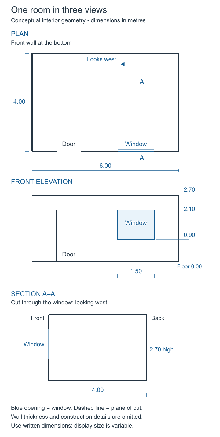
One imaginary room drawn three ways, with the same positions kept across all three.
- Observe
- Find the door and the window in the plan, then find the same two openings at the same left-to-right positions in the elevation.
- Interpret
- Each view answers a different question about one room; reading across them is how a drafter checks that the views agree.
- Do not infer
- Do not measure the screen. The stated dimensions, not the printed size, are the information.
- Try next
- Cover the section and try to predict what the cut will show before you look.
Sources and limits for this figure
Aligned plan, front elevation and section of one fictional room. The section cuts through the front window.
The same room is six metres wide, four metres deep and 2.7 metres high. In plan, the front wall is at the bottom. Measured from its left corner, the door occupies one to two metres and the window occupies 3.5 to five metres.
The front elevation keeps the same left-to-right positions. The door head is 2.1 metres above the floor. The window sill is 0.9 metres above the floor and its head is 2.1 metres above the floor, so the window height is 1.2 metres.
The section plane passes through x = 4.25 metres and looks towards the left side of the plan. The front wall is on the left of the section; the back wall is on the right. The door is outside this cut and is omitted. A dashed blue line and arrow identify the cut and viewing direction in this figure’s own legend.
Wall thickness and construction layers are omitted. The blue marks identify the window and section relationship; they are not an assertion of a universal professional line convention. Use the dimensions and labelled directions, not a ruler on this screen.
Original fictional teaching geometry — Created for this Fieldbook. Diagram conventions are stated locally; these are not surveyed or construction documents.
Source and rights:Original fictional teaching geometry
Created for this Fieldbook. Diagram conventions are stated locally; these are not surveyed or construction documents.
Building drawings divide a three-dimensional subject into views that answer different questions. This division makes complicated information manageable. It also creates a responsibility for the reader. You need to connect the views without assuming that any one of them tells the whole story.
Begin with a simple rectangular room. Imagine an empty room six metres wide, four metres deep and two point seven metres high. For now, disregard the thickness of its walls. These are the dimensions of an imaginary teaching space, not dimensions for constructing a building.
Stand outside its front wall. There is a doorway towards one end and a window further along. The doorway is one metre wide. The window is one point five metres wide. Its sill is nine hundred millimetres above the floor, and its head is two point one metres above the floor. The head is the top of the opening; the sill is its bottom.
An elevation describes a vertical face. Our front elevation shows the width and height of the openings in the front wall. It lets you compare their tops, see the window's position above the floor, and understand the wall's overall proportions. It does not directly show how far the room extends behind that wall.
A plan describes the arrangement as seen from above. In architectural work, a floor plan commonly represents a horizontal cut through the building. Think of removing the upper part so that walls and spaces can be understood together. Our simple plan reveals the room's six-metre width and four-metre depth. It locates the doorway and window along the front wall. Their positions can be related to corners and to the space inside.
The plan cannot, by its outline alone, establish the window's sill height. That missing information does not make the plan defective. It explains why another view is needed. A drawing set distributes information across related drawings, dimensions, notes and schedules.
A section describes a cut through the building in a vertical plane. Imagine slicing our room from front to back through the window. The section shows the floor, the room height and the window's position within the wall. A line on the plan identifies where this cut passes. The indicated viewing direction tells you which way the section looks.
Moving that cut changes what it intersects. A cut through the doorway will not produce the same opening as a cut through the window. This sounds obvious in an empty room. In a two-storey building, it is easy to forget. A section may pass through a stair, miss a bathroom, and reveal only part of a roof arrangement.
The companion drawing, One Room in Three Views, follows the same room and window across the views. The section passes through the window and omits the doorway, which lies outside its cut. Follow the window from its position along the front wall to its height above the floor. The purpose is to connect location with height. The diagram deliberately omits wall thickness and construction details so that those relationships remain visible.
Looking at the drawing adds something that listening cannot supply. You can track the cut line, compare the opening positions and notice which dimensions belong to which view. The spoken explanation gives those marks meaning. The drawing lets you examine their actual spatial relationship.
Size on paper and size in the world
A building is usually too large to draw at its actual size. Scale expresses the relationship between the drawing and the represented object. At a scale of one to one hundred, one unit on the drawing represents one hundred of the same units in the object.
Our six-metre room is six thousand millimetres wide. At one to one hundred, that width occupies sixty millimetres on a correctly sized drawing. The calculation divides six thousand by one hundred. It does not change the room. It changes the size of its representation.
Now consider a site twelve metres long. Twelve metres is twelve thousand millimetres. At one to one hundred, it occupies one hundred and twenty millimetres on paper. At one to two hundred, it occupies sixty millimetres. The second drawing fits more ground into the same space, but leaves less room for small details.
This is why a drawing set uses different scales. A site plan needs to show relationships across an entire site. A detail needs enough space to show a particular connection. Enlarging a detail is useful because the question has changed, from where a component belongs to how its parts relate.
Scale depends on the reproduced size. A drawing reduced to fit a page can still carry its original scale label even though the printed geometry has shrunk. A screen image can change size whenever you zoom. A number beside a dimension line and a length measured from a displayed image therefore have different evidential roles.
Before measuring from a drawing, establish its issue, units, reproduction size and instructions about scaling. If the written information conflicts with a measurement from the image, investigate the conflict. Quietly replacing a stated dimension with a ruler reading can conceal the very problem that needs attention.
Keep units visible throughout the calculation. Twelve divided by one hundred is zero point twelve, but that answer only makes sense if you remember the original twelve was metres. Zero point twelve metres is one hundred and twenty millimetres. Dropping units too early is a common way to make a plausible calculation produce an implausible building.
A line can do several jobs
On a building drawing, a line may represent an edge, a cut surface, an object beyond the cutting plane or a reference. These roles differ. Before interpreting a mark as a physical component, establish which role it performs in that drawing.
A dimension line, for example, helps describe a distance. It is not a cable, a wall or an element to be constructed. A line identifying a section cut locates a view through the building. It does not describe a proposed saw cut in the completed work.
Different line weights and patterns help separate these roles. Heavier lines can emphasise elements cut by a view, while lighter lines carry information beyond it. Dashed patterns can identify particular kinds of hidden or reference information. The exact meaning depends on the drawing conventions and legend being used.
Do not assume every dashed line means the same thing. One drawing may use it for an overhead element; another may distinguish an existing feature or a reference boundary differently. The reader needs the legend, notes and context, especially when documents come from different organisations.
In our room companion, the dashed blue line is explicitly identified as the section plane. Its arrow gives a viewing direction. That local legend makes the diagram interpretable without pretending it demonstrates every convention used in professional architectural documentation.
Patterns within a cut element can help identify materials or distinguish adjoining parts. Such a pattern is often called hatching. A hatch needs a meaning within the drawing set. Colour may assist a digital view, but information should remain distinguishable when a sheet is printed without colour.
An apparently simple black-and-white drawing therefore has a visual hierarchy. Some marks describe the building, some describe how it is viewed and others describe information about it. Learning to separate those layers is more useful than trying to memorise every symbol at once.
From a symbol to an object
A drawing can represent a complicated object using a simplified symbol. A door leaf and its path of movement, for instance, may be reduced to a line and an arc. The symbol helps a reader understand the opening and the direction of movement without showing every hinge and fitting.
The simplification has limits. The arc does not specify the door's mass, closing mechanism, handle or performance. A door identifier may refer to a schedule that supplies additional information. A detail may address its connection to the surrounding wall.
Schedules gather repeated information into an organised record. A window schedule can connect an identifier with size, type and other specified attributes. Its exact fields vary. The schedule and the drawing must use the same identifiers for the relationship to remain reliable.
Imagine a plan identifying a window as W-three. The schedule describes W-three as a particular opening, but an elevation labels the same apparent window W-four. The discrepancy might concern the identifier, the opening or an outdated issue. Similar location alone does not establish which document is correct.
A useful reading follows the identifier across the set and checks the associated geometry and notes. It preserves the discrepancy where the relationship fails. The reader should not choose whichever label makes the sheet look tidiest.
Other symbols represent fixtures, services or levels. Their detail is selected for the drawing's purpose. A plumbing fixture symbol locates the intended fixture but may not describe the full pipework arrangement. A structural symbol can refer to a member whose specification appears elsewhere.
This is why a legend is part of the information, not decoration at the edge of a sheet. It explains the agreed compression of meaning. When a symbol remains uncertain, consulting the author or the relevant specialist is more reliable than inferring a familiar object from a vaguely similar shape.
Orientation and viewpoint
Plans need an orientation. A north indication relates the drawing to a geographic direction under the stated convention. The top of a page is not automatically north. Rotating a plan to fit a sheet does not rotate the real site.
One room, another way of seeing
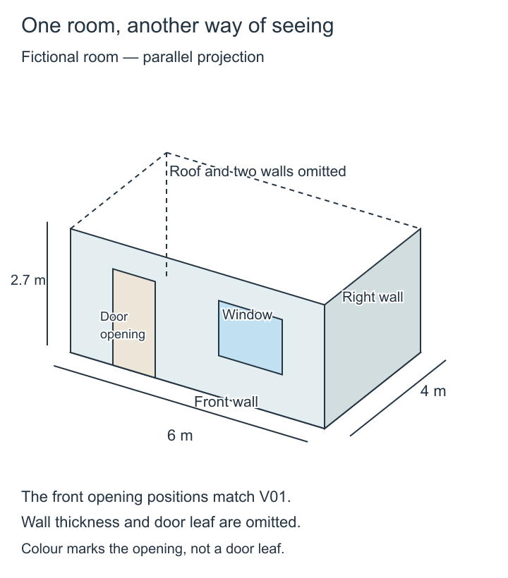
The same imaginary room again, this time as a single three-dimensional view.
- Observe
- Track width along the front face, depth along the right face and height vertically, then find the V01 door and window.
- Interpret
- A pictorial view connects the three directions at once; the separate plan and elevation still make individual positions easier to compare.
- Do not infer
- Do not read the sloping lines as sloping floors, or the omitted walls and roof as an absence in the room.
- Try next
- Return to V01 and name one thing each view shows that the other cannot.
Sources and limits for this figure
Parallel view of the V01 room with front door and window and right wall visible; roof and two walls omitted.
The front wall contains the same door and window as V01. Follow the width along the front face, the depth along the right face, and the height vertically. The sloping lines are a pictorial projection of horizontal building directions; the floor is not sloping.
This view uses the same six-by-four-metre room and 2.7-metre height. The door and window retain their V01 positions and heights. The roof, left and back wall faces, wall thickness and door leaf are omitted. The dashed upper outline identifies the missing enclosure’s extent.
The coloured door area marks the opening, not a depicted leaf or material. Both the upper dashed outline and rear dashed vertical indicate the omitted model extent. The view helps connect three dimensions, while the separate plan and elevation make selected positions easier to compare. This is a simplified spatial model, not a construction cutaway.
Original fictional teaching geometry — Created for this Fieldbook. Diagram conventions are stated locally; these are not surveyed or construction documents.
Source and rights:Original fictional teaching geometry
Created for this Fieldbook. Diagram conventions are stated locally; these are not surveyed or construction documents.
Orientation matters when interpreting solar access, exposure and relationships to streets or neighbouring land. It also helps connect a plan with observations made on site. A photograph facing one way and a plan rotated another way can be difficult to reconcile unless both viewpoints are identified.
Elevation titles may identify a direction or a named face. Read the title and the source convention rather than relying only on where the view sits on the page. “Front” can be ambiguous on a corner site or on a building with several public approaches.
Sections add another directional choice. The line identifies the cutting plane, while its viewing indication identifies which side is being described. Looking in the opposite direction can change what appears beyond the cut, even though the cutting plane stays in the same place.
Our room diagram places the front wall at the bottom of the plan. The section looks west through the window. This defined relationship explains why the front and back occur where they do in the section. Without that relationship, the reader would have to guess how the views connect.
Three-dimensional views can help build this connection. An axonometric view keeps parallel directions parallel in its representation. A perspective view more closely resembles the convergence seen from a viewpoint. Both can make an arrangement easier to recognise, but neither removes the need for dimensions and coordinated orthographic views.
The companion's parallel view returns to our same room. Its front wall retains the door and window positions, while the right wall reveals the depth. The roof and two wall faces are omitted. Trace the six-metre width, four-metre depth and 2.7-metre height in their different directions. The sloping lines on the page represent horizontal building directions; they do not mean that the floor slopes. The colour at the door marks the opening, not a depicted door leaf.
Orthographic views include the plans, elevations and sections used to describe the subject without perspective convergence. Their relative lack of pictorial realism is a strength for certain questions. They allow dimensions and alignments to be examined without the apparent size changes produced by perspective.
A rendered perspective may show a convincing room while concealing an unresolved connection outside the view. Realism can make a proposal easier to imagine, but it is not evidence that every part has been documented. Read the image according to its purpose.
Dimensions need endpoints
A dimension is a statement about a relationship between defined points, lines or surfaces. Its endpoints are part of its meaning. Six metres between external faces is not the same room size as six metres between internal finished faces.
Wall thickness explains the difference. Imagine two walls each two hundred millimetres thick. If a six-metre overall width includes both walls, the space between their inner faces is five point six metres. Subtracting two wall thicknesses, four hundred millimetres in total, gives that internal width.
This is a geometric example, not a specified wall assembly. Actual drawings may dimension to structural faces, centrelines, finished surfaces or other defined references. The reader must establish the convention before using the number to locate an object.
Dimension chains divide an overall distance into parts. Suppose three adjoining spaces are two metres, two point five metres and one point five metres wide. Together they total six metres if they share the stated endpoints and no additional thicknesses lie between them.
If the drawing also includes walls between those spaces, the simple sum may no longer describe the overall outside width. The question is not whether addition works. It is whether the quantities being added cover the same complete distance without gaps or double counting.
That reasoning is useful when a chain and an overall dimension disagree. Check endpoints, included thicknesses and revisions before assuming that a single number is a typing error. A mathematical inconsistency can expose a different geometric interpretation.
Levels need the same attention. A floor level, a ceiling level and an opening height describe different references. The difference between two levels can give a vertical distance, but only when both refer to the same datum and the intended surfaces.
Precision in the notation should also be interpreted carefully. A computer can display many decimal places without improving the underlying measurement. The number of digits is not a substitute for knowing the instrument, method and required accuracy.
Read across the views
Consider the window again, now with its surrounding room understood. The plan locates it along a wall. The elevation relates it to the facade. The section gives a vertical relationship through a particular cut. A schedule and details may add information about the selected unit and its interfaces.
Each view supplies a different part of an argument about the same proposed object. A useful reading moves between them and checks whether the relationships agree. It does not expect every sheet to repeat every fact.
Begin with identity: establish the project, sheet, issue and purpose. Then establish the view and orientation. Locate the object using its geometry and identifier. Finally, follow the references that provide the information needed for the question at hand.
Suppose the question concerns whether a bench fits beneath the window. The opening's location in plan is relevant, but its sill height and the bench's height also matter. The surrounding construction and installation allowances may introduce further requirements. A plan alone cannot settle the relationship.
If the question concerns how the window relates to an upper-storey opening, the elevation may reveal the intended alignment. A section may then explain a vertical offset caused by floor construction. The relevant route through the set changes with the question.
Drawing interpretation becomes easier as this habit develops. Marks stop being isolated symbols and become connected descriptions of space, materials and decisions. The reader can then identify both what a drawing communicates and what still needs another view or source.