

From Ground to Floor
Trace how footings, slabs and suspended floors meet the ground, with attention to site reports, movement, construction sequence, drainage and termites.
A level floor over changing ground
A finished floor can conceal very different construction beneath it. One house may sit on a slab supported by prepared ground. Another may have a timber floor carried above the ground on posts, piers or walls. A third may use a suspended concrete floor. The level surface underfoot does not identify the support system.
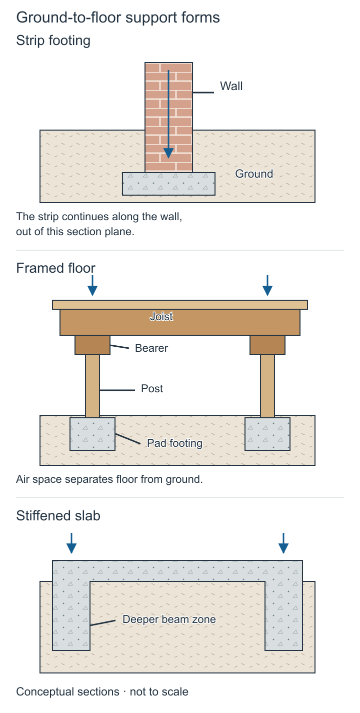
Three ways a floor meets the ground
Three conceptual arrangements show different ways loads reach the ground.
- Observe
- Follow the downward load line in each of the three arrangements until it reaches the ground.
- Interpret
- Each arrangement transfers load through different supported elements before it reaches the ground.
- Do not infer
- Do not read any arrangement as a footing design, a soil assessment or an approved detail. The three are conceptual comparisons and are not drawn to one common scale.
- Try next
- Say what each arrangement would need to be checked against before it could be used.
Sources and limits for this figure
Three conceptual sections: wall on strip footing, joist-and-bearer floor on posts and pads, and slab with deeper edge zones.
The upper section shows a wall transferring load to a strip footing and then the ground. The middle section shows floor joists bearing on a bearer, which transfers load through posts to pad footings. The lower section shows a slab supported at the ground with deeper edge zones.
Look for a continuous sequence of supported parts, rather than treating the floor surface as the entire system. The section through the bearer is an end view; it does not show the complete grid of supports in plan.
These are conceptual forms. Soil suitability, dimensions, reinforcement, connections, internal slab stiffening, damp protection, termite management and engineering design are omitted. The drawings cannot select a footing system for the fictional sites.
NCC 2025 Housing Provisions — Part 4.2 and its application conditions; governing edition still depends on jurisdiction and project.
Source and rights:Housing Provisions
NCC 2025 Volume Two and Housing Provisions. Read an application provision before its detailed pathway. Relevant teaching locations include structural provisions, glazing, fire safety, wet areas, amenity and safe movement.
The site connects these choices to real conditions. Slope affects the relationship between floor level and ground. Soil behaviour affects footing design. Access affects excavation, delivery and lifting. Water must still move through the site without creating unacceptable conditions around the building.
Return to the simple sloping site from the earlier companion. Its ground rises from one side to the other. Choosing a horizontal floor creates changing distances between the floor and the ground. Excavating, filling, stepping the building or suspending the floor are different responses to that geometry. None can be selected from the contour drawing alone.
The contour drawing describes the surface. It does not establish the material beneath that surface, its bearing behaviour or its response to moisture. Two sites with the same slope can need different footing systems. Ground shape and ground properties are separate sources of information that meet in the design.
Footings spread and transfer actions
A footing transfers building actions into the supporting ground. The foundation, in one common technical use, is that supporting ground itself. Everyday speech sometimes uses foundation for the constructed base as well. When reading a report, establish which meaning the writer intends.
Pressure relates force to the area over which it acts. Spreading a load over a larger suitable area can reduce average pressure. This principle helps explain the width of a footing beneath a narrower wall. It does not provide a footing size, because the ground and the structural system impose further conditions.
Ground can settle, swell, shrink or vary across a site. Fill may differ from undisturbed material. A former excavation can create a local change that is not obvious from the surface. A footing design needs to account for the relevant conditions rather than assume every point beneath the building behaves alike.
Reactive soils can change volume as their moisture conditions change. Uneven movement can distort a building. The movement of one part relative to another is often more troublesome than the same small movement occurring uniformly. Finishes, doors and services can reveal the consequences without revealing the underlying cause.
Site classification belongs to a defined investigation and design framework. It is not a colour chart for soil or a judgement made from one handful of material. A report's classification must be read with its observations, assumptions and limitations. The classification label is an input to design, not a complete footing instruction.
The classification letters describe expected ground behaviour as moisture changes. A generally covers sand or rock with little movement; S indicates slightly reactive clay. M indicates moderately reactive clay or silt. M-D is the Class M subdivision for deep-seated movement. P covers problem conditions, such as weak ground, instability or abnormal moisture. It is not simply another degree of clay reactivity.
These explanations help a reader understand a report. They do not supply the investigation and applicable classification method needed to assign a class to a site.
The 2025 Housing Provisions' simplified footing route is limited to specified Class A, S and M site conditions, with further building and ground restrictions. It expressly excludes the M-D category from those details. The letters alone therefore cannot establish eligibility. The invoking Volume Two provision, site report and all conditions must agree. An unresolved fill condition cannot be removed from the problem by repeating the otherwise familiar classification label.
Consider an apparently ordinary house site containing uncontrolled fill and the remains of an earlier building. A generic diagram of a slab on natural ground leaves out information that could govern the design. The useful first step is to clarify the investigation and proposed support, rather than copy the familiar diagram more neatly.
A report summary is the start of the reading
The linked STS report for 36 Avium Drive, Caddens, is dated 19 August 2020. Its site differs from Hillcrest. Its summary lists M and N2, the wind classification discussed in chapter thirteen. Read further: the ground discussion makes the M classification conditional and discusses P in relation to proposed fill.
Follow the summary into the main report, then its test-location plan, a borehole log and the limitations. The report describes two boreholes, not continuous observation of every part of the site. The location plan has an unknown scale. Neither the summary nor that plan supports measuring out a footing position with a ruler.
There is also a reference discrepancy. The fieldwork paragraph names drawing 20/1232, while the location plan and logs carry 20/2745. Preserve that discrepancy and ask for clarification. Do not silently repair it because the project identity otherwise appears consistent.
The site's history continues below the surface
Removed trees, altered drainage, old structures and previous excavation can affect present ground conditions. A site visit captures one moment in that history. A dry visit does not prove that the site never receives concentrated runoff. A recently cleared surface may conceal evidence that was visible in older photographs or records.
The design team therefore combines the investigation with other relevant evidence. A survey locates features and levels. Historical records may identify earlier uses. Drainage information helps establish possible water paths. The geotechnical report addresses ground questions within its stated scope. Each source contributes a different part of the explanation.
Imagine a proposed addition beside an existing house. Its floor is intended to align with the old floor. That alignment does not establish matching footing behaviour. The new structure may impose different loads or encounter different ground. The connection between old and new must account for the actual support and movement relationships.
Nearby excavation also matters. Removing ground beside a footing can affect support. There is no universal safe line that a novice can draw at a favourite angle for every soil and excavation. The geometry, depth, ground conditions and existing structure need appropriate assessment.
Footing forms and the slab assembly
A strip footing provides continuous support beneath a wall along its length. In a section cut across that wall, it can look like a wider base under a narrow upright. Its continuation out of the section plane is what makes it a strip, rather than one isolated block.
A pad footing is a discrete footing supporting a concentrated load, such as that received through a post or pier. Separate pads can support a raised floor through intermediate members. The floor spans between its supports; the ground between the pads is not performing the same role as ground directly beneath a ground-supported slab.
A stiffened slab combines a floor slab with deeper beam portions in a designed arrangement. The thin-looking floor area and deeper portions act within that system. It differs from simply pouring a flat sheet of concrete over whatever ground happens to be present. These descriptions explain common forms without assigning dimensions or a suitable soil class to any one of them.
A slab on ground receives support through the ground beneath it. Its shape and reinforcement form part of a designed system. Edge beams or other thickened portions may help carry assigned loads and manage movement. The smooth upper surface reveals little of that arrangement after construction.
Preparation beneath the slab matters. Unsuitable material, uneven support or inadequately prepared fill can undermine the assumptions behind the design. Compaction concerns changing the arrangement of soil particles to achieve specified properties. A surface that looks flat is not evidence that the required preparation has been achieved.
The slab assembly must also address moisture from the ground. A vapour barrier can help limit moisture transmission through the floor. Its continuity at joints and service penetrations is important. A punctured sheet or an uncoordinated pipe opening can interrupt the intended protection.
That barrier does not collect roof runoff or solve surface drainage. Nor does its presence establish a complete termite system. Several layers or components can occupy the same area while performing different jobs. Good section reading identifies each function before treating the assembly as one undifferentiated base.
Floor finishes add further conditions. Moisture remaining in or moving through a slab can affect some adhesives and finishes. A finish supplier may require particular substrate conditions. The structural slab specification and the finish installation requirements need to be coordinated; one does not automatically satisfy the other.
An accessible doorway illustrates the interface. A small level difference may improve entry, while external water must still be controlled. The threshold, adjacent paving, drainage and internal floor assembly need a connected solution. Removing a step from an isolated elevation is not enough to resolve the entrance.
A suspended floor carries its load elsewhere
A suspended floor spans between supports. Its load path does not rely on continuous ground support immediately beneath the occupied surface. This can help accommodate slopes and create space below, but it introduces its own structural and enclosure questions.
In a common framed arrangement, floor sheeting transfers load to joists: repeated, relatively closely spaced members supporting the floor surface. Joists can bear on larger supporting beams called bearers, or on walls or other designed supports. Posts or piers carry those supports towards the footings. The sheeting spans between joists, while the joists and bearers span across their own support intervals. Each stage gathers load from the stage above it.
The word span describes the distance between relevant supports. It is not always the same as the visible length of the piece. An element may continue across several supports or project beyond one. Knowing the support arrangement is essential before interpreting a member schedule.
Subfloor bracing and connections help resist lateral actions as well as gravity loads. A raised floor that appears well supported vertically may still need a defined route for wind forces. Posts alone do not explain that route. The connections at their tops and bases matter too.
Suspended concrete floors can be cast in place or assembled using precast systems. Temporary formwork and propping may support work during construction. In some systems a permanent component also has a structural role; in others it serves a different purpose. The drawings and product evidence must identify which arrangement is intended.
A concrete floor does not always require masonry walls below it. Suitable steel, concrete, timber or other designed supports may be used within an appropriate system. The material of the floor cannot establish the support material by itself.
Suspended floors also raise questions about services, insulation, sound and fire. The space below may make some services accessible, but pipes must still follow suitable routes. Cutting a joist to fit a waste pipe can interrupt the load path. A route needs coordination with permitted penetrations and structural design.
The construction sequence is part of the design
A completed drawing often shows every element in place. Construction passes through stages in which many of those elements are absent. A floor may receive temporary loads before walls and bracing are complete. A precast component may be stable only after its designated connections are made.
Temporary support is therefore a structural matter. It is not spare material left over until the building looks finished. The required support, installation sequence and removal conditions need to be established by the relevant design and work planning.
Imagine packs of masonry units delivered onto a new suspended floor. Their concentrated weight may differ greatly from the normal distributed use assumed for that floor. The fact that the finished building will contain masonry does not mean any construction-stage stacking arrangement is acceptable.
This is a useful question for a drafter to recognise early. Where will materials be delivered, stored and lifted? Which parts of the structure will be complete at that time? Identifying the dependency helps the responsible people resolve it before the site team faces the physical problem.
Four water paths at the base of a building
Roof water begins high on the building and needs a designed collection and discharge route. Surface water travels across the ground or paving. Subsoil water moves below the surface. Moisture vapour can pass through ground-contact construction. These paths interact, but they are not interchangeable.
Surface grading can help direct runoff away from vulnerable parts of a building. Finished ground and paving levels must be coordinated with floors, openings, cladding and inspection zones. A landscape change made late in the project can reverse that relationship.
Consider garden soil raised against a wall after handover. It may obscure an intended inspection zone, bridge moisture protection or redirect water. The building drawing and the landscape proposal need to communicate about the same finished levels. A building does not stop interacting with its site when the structural work ends.
Subsoil drainage needs somewhere suitable to discharge and a means of functioning over time. A buried drain without a resolved outfall is an incomplete idea. The design also needs to account for maintenance and the relevant authority requirements. Sending water away from one footing does not justify sending it onto a neighbour.
The term fall describes a downward change in level along a route. Its direction needs to be explicit. A drain or surface labelled with a fall must connect to the intended destination at workable levels. An arrow alone cannot demonstrate that the whole route is possible.
Termite management depends on continuity
Termite management considers the risk of concealed entry into susceptible primary building elements. A chosen system may use resistant materials, physical components, chemical components or a combination. The system's scope and evidence determine what it does.
A concrete slab can contribute to a termite-management arrangement without making the entire building termite-proof. Edges, joints and penetrations remain important interfaces. A pipe through the slab creates a condition that the system must address. Later alterations can introduce new conditions.
Inspection and maintenance form part of the intended arrangement. Concealing an inspection zone behind stored goods, paving or landscaping can make evidence of entry harder to see. Durable notices help identify the installed system and relevant maintenance information. They are useful records because occupants and maintenance contractors may change over time.
The important reasoning is continuity from the specified system to the built detail and its later care. A product name on a drawing does not establish that every penetration and edge has been resolved. Chemical application and system installation require their own current product and work instructions.
Making the section explain the floor
A useful ground-to-floor section shows more than a black line called slab. It locates the floor relative to finished ground. It distinguishes support from non-structural layers. It identifies the relevant moisture and termite interfaces, and it shows where other information is needed.
For a suspended floor, the section should make the void and support relationship understandable. For a slab on ground, it should distinguish the slab from preparation and ground beneath. Where the ground changes, the drawing needs enough context to explain the relationship rather than conceal it outside the crop.
A section can still be preliminary. It may refer footing and reinforcement design to engineering documentation. That reference is a dependency to follow, not evidence that the missing information is already on the architectural sheet. Recognising that distinction is part of reading the drawing accurately.
The floor is where site information, structure, moisture, access and construction sequence meet. Understanding those connections gives a reader a stronger basis for comparing methods. The choice is no longer simply concrete versus timber, or slab versus posts. It becomes a reasoned response to the building, the ground and the way the work will be carried out.