

Where Building Systems Meet
Read the junctions where support, drainage, glazing, fire protection, wet areas and services must work together.
A small junction can govern a large wall
A wall can contain suitable materials and still fail at a small opening. Water may enter around a window. A service penetration may interrupt fire separation. A pipe may occupy the space needed by a structural connection. The problem occurs where separately described systems must become one physical arrangement.
A junction is a place where elements meet. A detail drawing enlarges such a place so that relationships too small for the general plan can be explained. It may show a window sill, a roof-to-wall connection or a floor meeting a wet-area wall. Its value lies in showing how functions continue through the meeting point.
The first reading question is what the detail is cut through and in which direction it is viewed. The head is the top of an opening, the sill its bottom and the jambs its sides. A vertical section through a sill differs from a horizontal section through a jamb. Both can show the same window, but they reveal different geometry. A title and reference should let the reader locate the enlarged view within the larger drawing set.
The next question concerns the lines and layers. Some represent cut materials. Others show edges beyond the cut. A narrow gap may be intentional. A broken line may identify an element concealed in that view. The legend and notes establish the drawing's particular conventions.
Follow one function at a time
At a window, structure must support the opening and receive the window's own loads. Rainwater must be kept out or directed back outside. The thermal enclosure must account for the frame and perimeter. Air control must continue around the opening. Required fire, acoustic or impact performance may add other conditions.
Trying to understand every function at once can make the detail seem like an arbitrary collection of strips. Instead, trace one function through the junction. Follow the water-control layer towards the opening. Identify where it turns, laps or connects, and where collected water can leave. Then repeat the reading for support and other relevant functions.
This is a reading method, not a rule that every system needs a separate product for every function. One component can perform several jobs. Several components can also work together to perform one job. The important point is to understand the assigned functions and their continuity.
Imagine a sill that slopes towards the room. Even before selecting a proprietary flashing, the geometry raises a water-path question. Where would water on that surface travel? The answer may depend on hidden drainage and the complete window system, but the drawing should make the intended arrangement understandable.
The companion's sill illustration makes that question visible. Outside is on the left and the room is on the right. The blue receiving surface slopes outward, then turns down beyond the outer face. Its raised room-side end is an upstand. Follow the arrow along the outward slope and then down clear of the cladding. A discharge that instead ended inside the wall would leave the route unfinished.
The drawing also shows a discrete packer supporting the frame. Water passes between such packers, outside this particular section cut; it does not pass through the solid packing. This is a good example of a two-dimensional view needing an explanation of a three-dimensional arrangement. A continuous support placed across the entire drainage route would be a different condition.
This illustration explains a relationship, not a product installation. End dams, jamb connections, fixings, seals, tolerances and the complete window profile are not resolved here. A real system detail must answer the same question. How can the frame remain supported while water has a continuous route back outside?
Windows have several performance duties
Glazing is the glass or other relevant transparent infill within an assembly. A window also includes a frame, operating components, seals and fixings. The performance of a pane alone does not establish the performance of that whole assembly.
Wind applies loads to the window. The assembly transfers those forces to suitable surrounding construction. The building's other structural loads must not be unintentionally transferred onto the window. A frame squeezed by movement above it can become difficult to operate or sustain damage.
Weather resistance addresses water and air entering under relevant conditions. Impact safety addresses the consequences of people contacting glazing. Visibility helps people recognise a transparent barrier. Fall protection addresses the risk of falling through or from an opening. These functions overlap physically while requiring different evidence.
A safety-glass identification mark is not a substitute for making a large transparent opening apparent. A visibility marking is not proof that the glass has the required impact performance. A visually substantial frame is not proof of barrier capacity. Reading the evidence accurately means asking which question each marking or report actually answers.
An openable upper-storey window introduces the possibility of a fall. The relevant opening restriction, screen or barrier must suit the applicable conditions. An ordinary insect screen has not been established as fall protection simply because it fills the opening. Its appearance tells little about its resistance to a person pushing against it.
A schedule can identify glass and frame types, dimensions and operating arrangements. Installation and fabrication information resolve further details. Changing a fixed window to an opening window can affect ventilation, fall protection, weather performance and hardware. Keeping the same rough opening does not keep every performance condition unchanged.
Compare three other situations. A glazed door and its adjacent side panel lie along a person's route, so foreseeable contact and recognition of the glass matter. A shower screen adds wet conditions, repeated close contact and a particular framed or exposed-edge arrangement. A glass barrier at a level change must resist its assigned loads and prevent a fall. The pane may look similar in all three locations, but the complete assembly has different duties. Its specification must answer those duties rather than reuse one glass thickness by habit.
Water must leave the junction
Flashings direct water around vulnerable interfaces. At a wall opening, the head, jambs and sill meet different water paths. A head flashing deals with water arriving from above. A sill arrangement needs to manage water reaching the bottom of the opening. Side connections must integrate those parts with the surrounding wall.
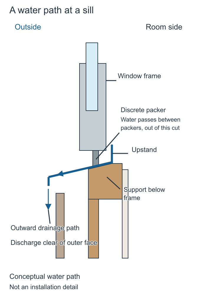
A water path at a sill
A conceptual sill section showing support and an outward-draining receiving surface.
- Observe
- Follow the receiving surface outward. Water passes between discrete packers outside this section cut, not through the solid packer shown.
- Interpret
- Support and drainage must work together; a continuous obstruction would change the drainage condition.
- Do not infer
- This is not an installation detail. The full profile, ends, jambs, seals, fixings and product conditions remain unresolved.
- Try next
- Explain what would change if a continuous support blocked the spaces between packers.
Sources and limits for this figure
Conceptual window sill with raised inner end and an outward fall discharging clear of cladding.
Outside is left and the room is right. Follow the blue receiving surface outward and downward, then beyond the outer face. The upstand rises at its room-side end.
The small support beneath the frame is a discrete packer. Water passes between packers, outside this particular section cut. It does not pass through solid material. A continuous obstruction across that route would change the drainage condition.
This drawing only explains support and drainage relationships. The full window profile, end dams, jamb connections, seals, fixings and product-specific installation are not resolved. It must not be used as an installation detail.
Your Home: cladding systems — Weather management and interfaces; original conceptual figure, not a copied product detail.
NCC 2025 Housing Provisions — Clause 7.5.6 outward drainage at openings; apply its actual conditions. Original conceptual drawing, not a reproduced NCC figure.
Source and rights:Cladding systemsHousing Provisions
Your Home: Construction systems, Lightweight framing, Brickwork and blockwork, Concrete slab floors and Cladding systems.
NCC 2025 Volume Two and Housing Provisions. Read an application provision before its detailed pathway. Relevant teaching locations include structural provisions, glazing, fire safety, wet areas, amenity and safe movement.
The arrangement is system-specific. A detail for one cladding and window type cannot automatically be transferred to another. The new combination may have different support, drainage, movement and fixing conditions. A source detail is useful only within the conditions it actually describes.
A cavity can provide a drainage route if the system is designed and built to use it. Its outlets and interruptions matter. A cavity filled with debris or sealed at the wrong point cannot be assumed to drain. The drawing should explain the route, while construction and inspection establish whether the route remains open.
Weatherproofing also has to coexist with movement. A rigid bridge across a moving junction may crack or tear adjacent layers. A sealant needs suitable joint geometry, compatible surfaces and the relevant installation conditions. It is not a universal substitute for a missing flashing or an unresolved change in level.
Fire separation is continuous construction
Fire separation aims to limit specified fire effects through or between parts of a building. Its requirements depend on the building and the particular relationship being protected. A wall near a boundary and a separating wall between dwellings are different conditions. They should not be merged into one generic fire-wall detail.
The wall must be considered with its openings, roof junctions and penetrations. A fire-resisting surface interrupted by an unsuitable opening no longer presents the same assembly. A ceiling or roof junction can create a route around the intended separation if the design does not resolve it.
Fire resistance can involve structural adequacy, integrity and insulation under a defined test or design basis. Structural adequacy concerns carrying the relevant load. Integrity concerns resisting the passage of flames and hot gases. Insulation concerns limiting heat transfer to the unexposed side under that basis. These meanings help explain why a fire rating belongs to a specified assembly and application.
Non-combustibility is a classification determined under the applicable test and code provisions. It is different from an assembly's fire resistance. Combining materials classified as non-combustible does not automatically produce the required separating wall. The system's thickness, joints, supports and penetrations still matter.
Consider a new pipe through a separating wall. The opening changes the assembly. The pipe material and size, the wall construction, the opening geometry and the tested or otherwise accepted protection system become relevant. A generic note to seal all gaps cannot identify the correct fire-stopping arrangement.
The fire-stopping system also has to be installed and maintained as specified. A later cable added through the same opening can change the arrangement. Recording the system and the penetration makes future alterations easier to assess. Concealing the junction behind a finish does not remove its ongoing function.
Bushfire asks a different question
Bushfire exposure concerns conditions such as embers, radiant heat and, at higher exposures, flame contact. The building envelope and its openings need to respond to the assessed conditions and applicable pathway. This is different from determining ordinary separation between a house and a boundary.
A landscape photograph can show vegetation, but cannot establish a bushfire attack level on its own. Assessment depends on defined site and hazard information. A designer must also establish whether the relevant jurisdiction designates the area and what requirements apply to the proposed work.
Gaps, vents, glazing and roof junctions can matter because they form routes into or vulnerabilities within the enclosure. A detail intended to manage condensation or ventilate a roof may therefore need coordination with bushfire protection. Solving one problem by opening an unprotected path can create another.
The same reasoning applies to decks and associated structures where the relevant provisions include them. The house cannot be considered as an isolated box while adjacent elements create exposure paths. The exact construction follows the assessed situation and approved design evidence, rather than a universal sketch labelled bushfire safe.
Wet areas contain deliberate water exposure
A shower is different from a room that may occasionally receive a spill. Its surfaces experience repeated wetting. Water can reach joints, corners, penetrations and the drain. A wet-area system must manage those routes through a suitable combination of substrate, waterproofing, finish and drainage.
Waterproof describes preventing water penetration under the relevant conditions. Water-resistant describes restricting water movement while resisting degradation when wet. The distinction applies to the specified materials and system, not merely an adjective on packaging. Tiles and grout should not be assumed to form the entire waterproofing system. The visible finish can shed much of the water while concealed layers perform essential protection.
The substrate supports the waterproofing and finish. Its movement, condition and compatibility affect the layers above it. A membrane needs continuity at corners and penetrations, together with the movement accommodation specified for that system. A neat tile pattern cannot demonstrate that the concealed membrane remains continuous.
The drain connection is particularly important. Water reaching the waterproof layer needs an appropriate route into drainage. A drain flange provides a connecting surface around the drain opening for the waterproofing system. A hole cut through tile is not a complete description of that connection. The membrane, flange and surrounding construction must work together within the selected system.
A screed is a layer used to form or finish a surface, often including the required falls. Some wet-area systems place waterproofing above it; others use a different permitted arrangement. There is no single layer order that can be copied into every shower detail without examining the chosen pathway and product requirements.
Falls direct water towards the intended waste. The finished surface, thresholds and adjacent spaces must be coordinated with those falls. A hob is a raised edge around a shower area. A level-entry shower can improve access, but needs a carefully resolved water-control arrangement. Removing the hob from a familiar detail does not by itself produce that arrangement.
Not every bathroom floor has identical drainage requirements. Shower areas require their relevant waste arrangements; other wet-area conditions vary with the applicable provisions and design. A handheld bidet spray can introduce a different wetting condition from a plain toilet installation. The actual fixtures therefore influence the waterproofing question.
Services occupy real space
Plans often use small symbols for fixtures and equipment. Behind those symbols are pipes, ducts, cables, clearances and access needs. A symbol's size on a general plan does not establish the space required by the installed system.
Waste pipes need suitable routes and levels. Ducts need space through ceilings and around structural members. Equipment may need access for filters, valves, replacement or maintenance. These requirements can affect room layouts and the shape of the building before installation begins.
Imagine a bathroom placed above a living room. The preferred waste route crosses the supporting floor structure. The ceiling below has a carefully planned height. An unresolved pipe cannot simply occupy the same physical space as a joist. The team must coordinate the fixture location, structural system, service route and ceiling arrangement.
One response could move the fixture so the waste reaches a suitable route with less conflict. That changes the bathroom's use and joinery relationships. Another could reserve a service zone below or beside the structure, changing the ceiling or bulkhead. A revised structural arrangement may also be investigated by the responsible designer. Comparing those responses means checking the consequences in both rooms, not choosing the route that looks shortest on one plan.
The presence of a service zone on an architectural plan can reserve useful space. It does not prove that every service fits or that the zone can be accessed. Consultant drawings and equipment information add the dimensions and relationships needed for coordination.
Access panels create further interfaces. A panel through an acoustic or fire-resisting assembly must suit that assembly's requirements. A maintenance opening near a wet area must not undermine water control. Accessibility for repair needs to be designed alongside the performance of the surface being opened.
A detail is a decision with conditions
An informative detail states or references the systems it joins. It identifies relevant materials, dimensions, levels and installation dependencies. Its callout leads back to the general arrangement so the reader can understand where and how often it applies.
A standard detail within an office library is a starting resource, not automatic project authority. Its materials, climate assumptions, loads and reference editions may differ from the current project. The responsible designer needs to establish suitability and resolve changes before it becomes part of the issued documentation.
When a detail seems contradictory, the useful response is a precise question. Identify the drawing, location and competing information. Explain the physical consequence: water appears directed inward, two components occupy the same space, or a required layer has no shown continuation. That gives the team something concrete to resolve.
Junction reading turns a collection of material names into an explanation of performance. Follow support, water, air, heat, fire and access through the places where systems meet. The drawing becomes easier to interpret when every visible line is connected to a physical purpose and every missing relationship is recognised as a question.