

Turning Observation into a Measured Record
Turn observations into a traceable measured record, with explanations of tape and laser references, field sketches, photographs and measurement checks.
Before the first number
A measure-up translates a physical place into a record that someone else can interpret. The instrument supplies only part of that record. The person measuring chooses the feature, the endpoints, the method and the way the result is connected to the drawing.
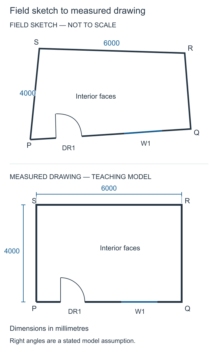
Field sketch to measured drawing
A rough field sketch above the measured plan that was produced from it.
- Observe
- Match each corner name and opening in the sketch to the same item in the measured drawing below.
- Interpret
- A field sketch is a record of what was measured; the measured drawing is an interpretation of it, and the names are what keep the two connected.
- Do not infer
- Do not treat the sketch's proportions as measurements, or the measured drawing as evidence that nothing was missed on site.
- Try next
- Sketch a room you are in and label the endpoints you would need before you could draw it.
Sources and limits for this figure
A rough room sketch above a measured rectangular plan, keeping corner names and openings consistent.
P is the front-left corner, Q front-right, R back-right and S back-left in both records. DR1 identifies the door and W1 the window. The rough sketch is not to scale.
The lower plan uses the fuller fictional dataset: overall interior dimensions 6000 by 4000 millimetres, right angles assumed, door offsets 1000 and 2000 millimetres, and window offsets 3500 and 5000 millimetres from P along the front wall. These opening offsets are additional supplied data; the two overall lengths shown on the rough sketch do not establish them.
The point is the traceable translation from an observed record into geometry. On a real job, opening offsets and squareness need their own measurement and checks. The diagram supplies no evidence of an actual inspection.
Original fictional teaching geometry — Created for this Fieldbook. Diagram conventions are stated locally; these are not surveyed or construction documents.
Source and rights:Original fictional teaching geometry
Created for this Fieldbook. Diagram conventions are stated locally; these are not surveyed or construction documents.
Begin by understanding the information required and the safe access available. An overall room dimension, an opening width and a height above the floor are different measurements. The same tool may be suitable for each, but the references and conditions differ.
Existing buildings also resist tidy assumptions. Corners may not be square, surfaces may not be straight and finishes may conceal the structural faces. A useful record describes the place encountered rather than forcing every measurement into an ideal shape.
A measurement needs an identity
Suppose a field note records a wall as six metres long. A drawing shows six point one metres. Before deciding that either is wrong, establish what each dimension describes. One may run between internal finished faces. The other may refer to a different pair of surfaces. The drawings may also belong to different revisions.
A useful measurement record identifies the feature, its endpoints, the unit, the date and the source. A photograph can help show the endpoints. A sketch can relate the measurement to surrounding features. Neither becomes reliable merely because it looks neat.
Imagine a photograph labelled only “wall”. A colleague may not know which wall it shows or whether it was taken before an alteration. A simple identifier linked to the site sketch makes the photograph more useful. If the sketch changes, the relationship must remain understandable.
The same principle applies to a survey supplied by another professional. Its title, date, revision, stated datum and scope matter before any numbers are transferred. An accurate number copied from the wrong issue can produce an inaccurate conclusion.
When a discrepancy remains, describe it precisely. Identify the two sources and the feature they appear to describe. State the conflicting values and the decision that depends on resolving them. This gives the responsible person something concrete to investigate. It is more useful than saying that the drawings do not match.
For our example, imagine the field sketch identifies measurement M-one between the room's internal finished faces. It records six point zero metres on Tuesday. Drawing A-one, revision C, shows six point one metres, but the dimension's endpoints are unclear in the supplied image.
A useful query links those records and asks which faces the drawing dimension describes. The drafter refers it to the supervising designer, who can involve the drawing's author or arrange a measurement check as needed. It explains that the discrepancy affects the proposed joinery layout. The field measurement remains recorded as taken; the drawing remains identified by its issue. Until the endpoints and current issue are confirmed, neither value silently replaces the other.
Straight, horizontal and sloping distances
A distance has a direction. Measuring along a slope gives a different result from measuring the horizontal distance between its endpoints. The distinction matters when transferring site information into plan, because a plan generally represents horizontal relationships.
Imagine two points separated by four metres horizontally and three metres vertically. The straight sloping distance between them is five metres. This is the familiar three-four-five right triangle. Its three lengths describe different sides of one shape; they are not alternative readings of the same side.
Entering the five-metre sloping reading unchanged as the plan distance would be wrong. The established geometry gives a horizontal distance of four metres. The instrument could have measured the sloping line correctly while the drawing used that result incorrectly.
An indirect calculation can connect those distances when the geometry and inputs are established. It cannot correct an unidentified target or an uncertain endpoint. Before considering a formula, establish what was actually measured and which distance the drawing needs.
The same idea appears inside a room. A laser aimed diagonally upwards measures a line to the selected target. That line is not automatically the room's horizontal width. An instrument's indirect modes require their own method and conditions; a useful-looking result does not remove that dependency.
Using a tape as a measuring system
A tape carries a graduated scale along a physical length. Its reading depends on the tape's alignment, support, endpoint and condition. A sagging tape or an oblique path can describe a different distance from the one intended.
Read the scale and units before recording the result. Mixed units or a misread graduation can produce a plausible number with the wrong meaning. Keep the tape's route connected to the sketch so that another reader can understand the distance it represents.
Some retractable tapes have a deliberately moving end hook. Stanley explains that this movement compensates for the hook's thickness in different measuring situations. Movement is therefore not automatically damage. That does not mean a bent or damaged hook can be assumed accurate.
The tool's instructions and condition should guide its use. A damaged scale, distorted blade or uncertain endpoint affects confidence in a reading. Checking the tool is different from checking whether the building is square or whether the right feature was selected.
For a long distance, maintaining the intended line can be as important as reading the graduation. Avoid assuming that a tape following irregular ground gives a horizontal plan distance. A suitable method must establish the relationship needed without creating unsafe access or uncontrolled tension.
Repeated measurement can reveal inconsistency. If the same endpoints produce noticeably different readings, investigate the method and conditions. Averaging several readings does not automatically remove a consistent error, such as measuring from the wrong face every time.
A laser still needs a reference
A laser distance measurer determines a distance along a selected line. Its reference point may be the front or rear of the instrument, or another defined point. Selecting the wrong reference can shift every result while leaving the display apparently precise.
The Bosch manual for the GLM fifty twenty-seven family illustrates these dependencies. It distinguishes measurement references, display increments and accuracy under stated conditions. It also addresses temperature changes, instrument knocks, stability and unobstructed optics. These are model-specific instructions, not a universal procedure for every device.
The manufacturer warns that viewing glasses are not laser eye protection. Safe use includes avoiding eye exposure and following the device's actual safety information. A visible dot makes aiming easier; it does not make the beam an appropriate pointer towards people.
Target surfaces and surroundings can affect measurement. Bosch's online guidance identifies difficulties involving transparent, reflective, rough or sloping surfaces and changing conditions along the beam. Understanding the target helps explain why a number that appears immediately may still need checking.
The displayed increment is the smallest step the screen reports. Accuracy concerns the relationship between the result and the distance being measured under defined conditions. A screen displaying half-millimetre steps does not prove that every field result is accurate to half a millimetre.
Consider an imaginary instrument displaying two thousand point zero millimetres. The decimal place describes the display. It does not tell us whether the target was the wall face, a projecting trim or an object in front of the wall. Resolution cannot answer a question of identity.
An accuracy check compares readings with an appropriate known reference under a defined method. That is different from repeating an unknown room dimension and obtaining similar values. Similar readings show consistency in that situation; they do not independently establish the true distance.
Retain a check record where workplace procedures require it. A result obtained before a damaging knock may not answer a question about the instrument afterwards. Equipment history, conditions and method matter alongside the number.
What a string line supplies
A string line provides a visible physical reference between established points. It has no graduated scale of its own. Measurements taken to or from it depend on knowing what the line represents and how it has been established.
Imagine a wall whose face varies slightly along its length. A straight reference beside it can help describe offsets at identified locations. The offsets relate the irregular surface to one common line, rather than treating each local surface as a new reference.
The line is not automatically horizontal, square to another feature or coincident with a legal boundary. Those are separate geometric or surveying claims. A taut-looking line may still need its alignment and support checked for the intended purpose.
Equal spacing between two lines at their ends does not, by itself, prove that the resulting arrangement has right angles. A slanted parallelogram can have parallel opposite sides. Parallel describes a relationship between directions; perpendicular describes a right angle between them.
A real setup also introduces physical risks. Lines can obstruct movement or create trip hazards, and supports need an appropriate controlled arrangement. The location and method must suit the inspection conditions. A conceptual reference line does not authorise fixing into a structure or driving supports into unidentified ground.
A sketch that can become a drawing
A field sketch need not be a polished miniature of the final drawing. It needs to preserve the relationships required to make that drawing accurately. Clear feature identifiers and dimension endpoints can be more valuable than attractive shading.
Start with the overall arrangement and add information in a way that preserves context. A room can be linked to an adjoining space, a window to its wall and a photograph to its viewpoint. Separate detail sketches can enlarge a complicated area while retaining a reference back to the main sketch.
Suppose a recess interrupts a wall. A single overall dimension does not describe the recess's position or depth. Recording its two ends and its offset from the main face allows the later drawing to reconstruct the relevant shape.
Avoid filling a sketch with unlabeled numbers. A dimension written near a corner may become ambiguous once several lines meet there. Extension marks, identifiers and short notes help preserve what was measured. If access prevented a reading, show the gap rather than inventing a neat closure.
Distinguish dimensions measured directly from those calculated or supplied by someone else. A calculated remainder can be useful, but its reliability depends on the inputs. It should not quietly become another independent field measurement when the drawing is produced.
For example, subtracting two known lengths from an overall length gives a remaining segment only if the endpoints cover the same complete line. A wall thickness or offset omitted from that chain changes the result. The sketch is what makes the arithmetic's geometry inspectable.
Photographs are records of viewpoints
A photograph can preserve visible form, finishes, condition and context. Its usefulness increases when the location, direction and date are identifiable. A sequence of images without those relationships can be surprisingly difficult to interpret after a visit.
Use wider views to establish context and closer views to record detail. Link them through the sketch or an agreed identifier. A close view of a crack or junction should be recoverable within the larger building arrangement rather than remaining an isolated image.
Perspective changes apparent size. An object closer to the camera looks larger than an equal object further away. A ruler or known object in an image does not automatically make every other part measurable, especially when they lie on different planes.
Photographs also conceal what is outside the frame or behind a surface. A visible stain can support a condition record without proving its cause. A ceiling photograph cannot establish the full arrangement of concealed services. Record the observation at the level the image supports.
Respect the access and recording arrangements for the property. An inspection may involve occupied rooms, documents or personal possessions. Images should serve the agreed project purpose and be stored and transmitted through the appropriate workplace process.
From field information to a measured drawing
Back in the office, collate the sketches, photographs, measurements and supplied survey information before tracing a clean outline. Confirm that identifiers still connect. Resolve obvious transcription questions while the visit remains fresh, preserving original records rather than overwriting them.
The measured drawing represents existing conditions within the scope of the collection. It is different from a proposed design. Its date, source and limitations help others understand how it may be used and where additional investigation is needed.
Begin with established reference geometry and add the measured features. Check overall relationships against the dimension chains. Compare openings with photographs and adjoining views. A drawing that closes neatly on screen may still conceal a mismatch in the source measurements.
Software can encourage idealisation. An automatic right-angle setting may square a room that was not measured as square. A copied symbol may imply a standard fixture size that has not been established. The drawing should not acquire unsupported certainty through convenient defaults.
Where records conflict, retain the discrepancy and refer it through the responsible process. Identify its effect on the proposed work. A small uncertainty may be immaterial to an early site study but significant to fitted joinery or an interface with existing construction.
This connects measurement accuracy with purpose. More digits are not always more useful. The necessary confidence depends on the decision and the workplace requirements. Instrument capability, collection method and design tolerance should remain distinguishable.
Seeing a field record become a drawing
The companion places a rough field sketch beside a measured teaching plan of the same fictional room. The corners remain P, Q, R and S. The front wall stays at the bottom of both views. Keeping these identities stable is more useful than making the sketch look polished.
The measured plan is based on a fuller fictional record than the two overall lengths alone. The room is taken as rectangular, with a front length of six metres and a depth of four metres. From the front-left corner, the door opening begins at one metre and ends at two metres. The window begins at three and a half metres and ends at five metres. These positions are measured along the same front wall.
An illustrator could draw those openings anywhere and still produce a neat rectangle. The record prevents that arbitrary choice. On a real inspection, the offsets, endpoints and checks would have to be observed and retained. Two overall lengths alone would not establish that the room has right angles or that the openings occupy these positions.
More data, the same need for interpretation
Contemporary surveying and recording tools can capture information far beyond a basic tape measure. Satellite positioning, laser scanning and aerial imaging can support site analysis. Their usefulness still depends on reference systems, conditions, processing and the purpose of the record.
Global navigation satellite systems are commonly shortened to GNSS. They provide position observations using satellite signals and associated methods. Geoscience Australia explains how correction services and compatible equipment can improve positioning. That capability is not a guarantee for every phone or every location.
Obstructions, equipment, methods and reference information matter. A coordinate should retain its datum and quality context. It does not become a legal boundary determination merely because it has many decimal places or appears over an aerial image.
Laser scanning records many measured points, often presented as a point cloud. The cloud can help describe visible surfaces and support later drawing or modelling. Dense points do not establish that every surface was captured or that hidden conditions are known.
Turning a scan into a model introduces interpretation. Software and people identify surfaces, edges and objects within the data. A smooth wall in the resulting model may be a fitted representation rather than a direct record of every irregularity. The model's assumptions need to remain understandable.
Drones can carry cameras and other sensing equipment. Their use involves aviation requirements as well as the site's access and recording arrangements. Australia's Civil Aviation Safety Authority distinguishes operational categories and conditions; a small aircraft is not automatically unrestricted.
Data age deserves the same attention as equipment capability. A recently published online terrain service may contain observations collected years earlier. Grid spacing is also different from positional or height accuracy. Read metadata rather than treating a current web address as a current survey.
The tools change how information can be collected. They do not remove the need to identify what was measured, how it was processed and what the result can establish. A dependable measured drawing remains a reasoned record of a place, with evidence and limitations that another person can follow.