THE DEMOLITION SUPERVISOR’S FIELDBOOK / CHAPTER 39
Part VI · Plans, structures and engineering interface
Demolition plans, drawing views and specifications
Plans, elevations, sections and details describe different aspects of a structure. Their references, dimensions and notes work with specifications and reports to define the demolition boundary and its interfaces.
Each view answers a different spatial question
A drawing is a selected representation of a place or object, not the object itself. A site plan shows the relationship between the work and its surroundings: boundaries, access, nearby structures and other site features. A floor plan shows a horizontal view through a building at a stated level. An elevation shows a vertical face. A section shows a cut through the construction, helping explain heights, depths and relationships hidden in plan view.
A detail enlarges a particular connection or local arrangement. It may explain a junction that is too small to understand on the general drawing. A schedule organises repeated information, such as types of doors, finishes or members. An isometric or other three-dimensional view can help orientation, but it does not replace the dimensions, notes and controlling details.
Imagine a rectangular enclosure with a canopy. The floor plan shows where the canopy sits beside the enclosure. An elevation shows how high it is. A section may reveal whether it connects to a wall or stands on independent supports. A connection detail may explain the actual attachment. No single view necessarily answers all these questions.
01 / DRAWING INTERPRETATION · CHAPTER 39
Step inside the drawing.
A furnished home. A line on its plan. A different way to see the same space.
CPCCDE3027
ONE IMAGINARY CONTEMPORARY HOME
Loading the furnished home…
Front / livingDrag to cut into the same modelRear / mezzanine
OBSERVE
Tall glazing lights the living room. The open stair rises to a rear mezzanine. Compare the furniture, balustrades and upper floor as you switch views.
INTERPRET
The plan fixes the section’s location and direction. A cut through the stair differs from a cut through the mezzanine—even within the same building.
DO NOT INFER
These are illustrative proportions, not construction documents. Visible form does not establish structural support, compliant stairs or connection details.
GROUND PLAN / A–A LOOKS TOWARDS REAR
SECTION A–A / CUT FEATURES ONLY
READ THE RELATIONSHIP
Height is visible in section
A plan can locate the living room without revealing that it opens through two levels. The section makes that vertical relationship visible.
Roof omitted in the 3D cutaway so you can inspect the rooms. The section retains its outline. Interiors beyond the cut are simplified in the line drawing.
Try next
Start inside, then move the cut towards the rear. Find the narrow zone where the section crosses the staircase. Continue until the mezzanine floor enters the section.
Source, assumptions & limits
Original fictional contemporary home designed for comparing representations. User-supplied exterior and interior photographs guided the architectural character, furniture, stair, timber detailing and light; none is reproduced or treated as a measured source. This replaces the earlier generic single-storey enclosure; it is not a reconstruction of a Fieldbook case. All three-dimensional views use one model. The line drawings share its envelope, mezzanine and stair geometry. Room furnishings are intentionally omitted from the section.
Lighting is illustrative, not a daylight, solar or energy analysis. No site compass orientation, member capacity, connection design, staircase compliance or construction approval is established.
Original generic learning model. It establishes no condition, capacity, approved method or release for a real project. Qualified structural review is pending.
The references connect the views. A section marker points to another drawing or location; a detail callout does the same at a finer scale. If that referenced sheet is missing, the information chain is incomplete. Do not substitute a plausible-looking arrangement. The type of view determines which spatial relationship it can establish.
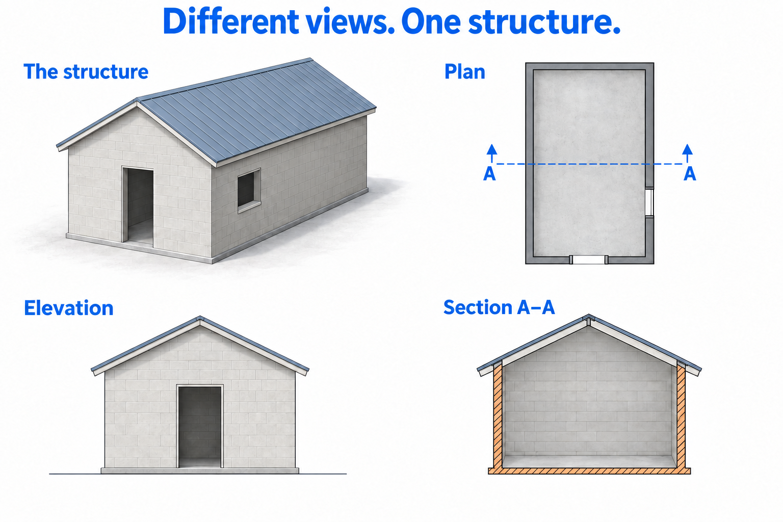
Plan, elevation and section
Drawing views describe different spatial relationships within the same structure.
A plan shows the horizontal arrangement viewed from above. An elevation shows the vertical outline of an external face. A section represents a cut through the structure, revealing internal relationships between elements such as roofs, walls and floors.
Drawing references connect these views to orientation, levels, dimensions and details. A plan may locate a connection without establishing its height; an elevation may show its external position without revealing a concealed arrangement. A missing referenced section or detail leaves an information gap.
The illustrated views are not to scale. Apparent line thickness cannot establish structural support, and dimensions cannot be measured from these shapes. On an actual drawing, interpretation depends on the project identity, revision, issue purpose, legend, units and applicable notes.
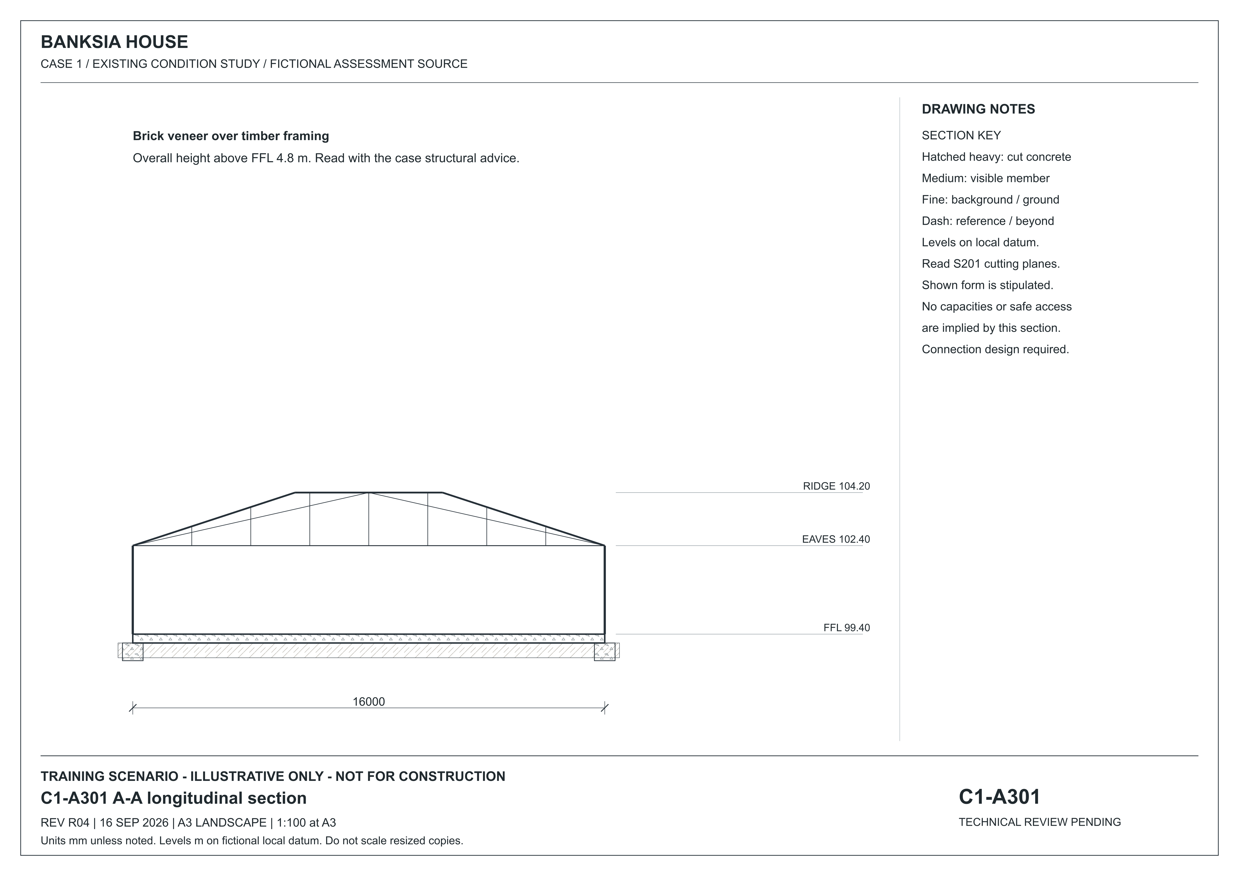
A-A longitudinal section
CONTROLLED FICTIONAL TRAINING RESOURCE Use the record and its stated limitation. Do not infer hidden support, services or approvals from the image alone.
C1-A301 R04 – A-A longitudinal section. A-A longitudinal section of Banksia House, identifying floor, eaves and ridge levels and the stated structural system. Local datum, not an engineering design. Reproduced in this guide at reduced size; use written dimensions, not a ruler on this page.
Use the record and its stated limitation. Do not infer hidden support, services or approvals from the image alone.
This visual is draft case-study teaching material. Reading it is not an inspection, a measurement or evidence of performance.
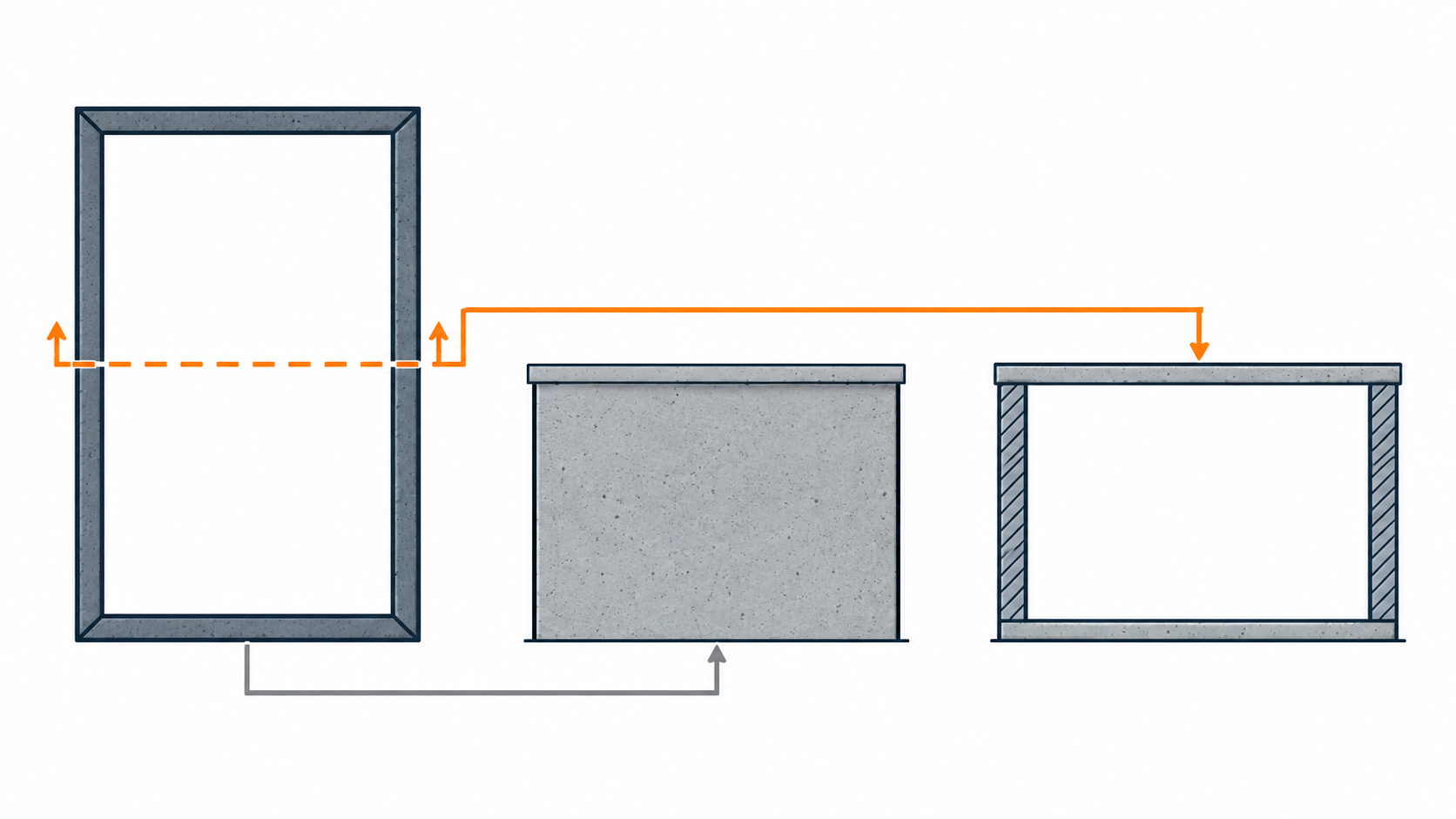
Plan, elevation and section
LEARNING AID A generic learning aid explains a principle. It does not establish a project fact, hidden condition, capacity, approval or work release.
Left: plan viewed from above. Centre: exterior elevation. Right: section through the indicated cut, revealing the interior and cut walls. Arrows connect the viewpoints. These are schematic views, not equal-scale drawings; do not measure or derive dimensions from them.
A generic learning aid explains a principle. It does not establish a project fact, hidden condition, capacity, approval or work release.
This visual is draft case-study teaching material. Reading it is not an inspection, a measurement or evidence of performance.
Architectural, structural, services and demolition information
Architectural drawings commonly describe layout, dimensions, finishes and intended use. Structural drawings describe the supporting system, members, connections and relevant design requirements. Services drawings address systems such as electrical, hydraulic, mechanical or fire services. Demolition drawings identify the intended removal and retention scope. Their information overlaps, but their purposes are not identical.
A wall shown on an architectural plan is not automatically classified as load-bearing or non-load-bearing. A service line drawn through an area is not proof of its current physical route or isolation status. A demolition hatch identifies an intention to remove something; it does not independently establish the method or confirm that the remaining structure will be stable. Those conclusions need their appropriate evidence.
The drawing register helps identify the current coordinated set. Related reports can supply information that is not legible from lines alone, including hazardous-material findings, structural assumptions, ground conditions or survey limitations. The demolition work plan then connects the proposed work to those inputs and to the controlled method.
Related site documents answer distinct practical questions. A traffic management plan describes the controlled movement and separation arrangements, not structural capacity. A dilapidation or existing-condition report records observations for its stated survey scope, not a demolition design. A hazardous-material audit identifies findings and investigation limits relevant to exposure and material handling. Site instructions communicate defined directions through the project's authority system; they must remain consistent with the controlling technical information. Reading these documents together helps reveal an unresolved interface instead of assigning every decision to the demolition drawing.
For example, an architectural plan may show an open internal space while a structural drawing shows a supporting member crossing it. That is not necessarily a contradiction; the architectural view may omit overhead structure. The view and level represented may explain the difference. If the documents still conflict, the difference must be resolved through the project's information process. Choosing the more convenient drawing would conceal the uncertainty instead of explaining it.
Drawing identity, location and references
Before using a dimension or symbol, establish which document you are reading. The title block normally identifies the project, drawing title and number, author, revision, issue date, issue purpose, units and scale information. The exact arrangement varies. A familiar logo or convincing layout is not evidence that a drawing is the authorised issue for the work.
Next, identify the represented level and orientation, then the work boundary. Distinguish existing, proposed, removed and retained elements using that drawing's legend and notes. Follow references to sections, details and schedules. Read general notes with local notes, because a condition applying to the whole package may not be repeated beside every element.
A retained wall may be defined on a plan at a particular grid. Its roof connection may appear in a separate detail, and its temporary demolition condition in a structural report. The location links these documents and makes a missing reference apparent.
Marking a personal copy can help understanding, but it must not create an unofficial design instruction. Site observations, queries and approved changes should remain distinguishable. A note saying suspected service route records uncertainty; a note saying service isolated makes a different claim and needs its own evidence. Keeping these categories distinct shows which information comes from the issued design, which records an observation and which remains to be confirmed.
In the Banksia House source family, start with C1-A101-R04, then connect C1-S201-R04 to the A-A and B-B sections, C1-A301-R04 and C1-A302-R04. Find the sheet identity before following the section reference. The site plan places the building and its surroundings. The structural reference plan and sections explain the stipulated construction and vertical relationships. Written dimensions remain the source of measurement; a reduced illustration is not a calibrated print.
Riverbend uses the same reading discipline with its own C4-A101-R04, C4-S201-R04, C4-A301-R04 and C4-A302-R04 sheets. Confirm the C4 identity before transferring a reference. Follow the industrial grid and the section direction together. A spacing along the building is not automatically a member length across it.
For Cardwell, begin with UP070, the detail and contour survey, and UP010, the identification survey. Add UP091, the tender addendum, to understand the stated removal scope and document history. The source index supplies exact filenames. UP052 contains proposed architectural information; it must not silently replace the existing footprint. Reading order follows the question being answered, not the apparent attractiveness of a drawing.
Interpreting a control record
A control record for a material-transfer area needs to identify the activity, location, revision and intended use. These details establish whether the document applies to the work. Its supporting information and unresolved assumptions are equally important: changing a heading does not make an unrelated record applicable.
A hazard entry must explain the route to harm. Terms such as plant or debris identify a subject but not the exposure. The record needs to establish how movement or material could reach workers, visitors, neighbouring property or an environmental receptor. Deliveries and changing work areas can alter those pathways.
The control entry distinguishes measures that are proposed from those already implemented. It identifies how each measure reduces exposure, who establishes and maintains it, and what technical information it depends on. Exclusion distances and load limits require the relevant site-specific basis; they cannot be derived from a generic form.
Verification must address the condition being relied upon. A photograph may establish the location of a sign, but it cannot establish the capacity of a structural support. A signature may record acknowledgement without verifying the assumptions behind the arrangement.
If a delivery blocks the planned route, the review must address the changed movement and exposure. The revised arrangement must be communicated and obsolete instructions withdrawn from use. Traffic arrangements, the demolition work plan, relevant safe work method statements, emergency access and briefings must remain consistent. A permit authorises a defined activity under specified conditions; it does not replace unrelated technical confirmations.
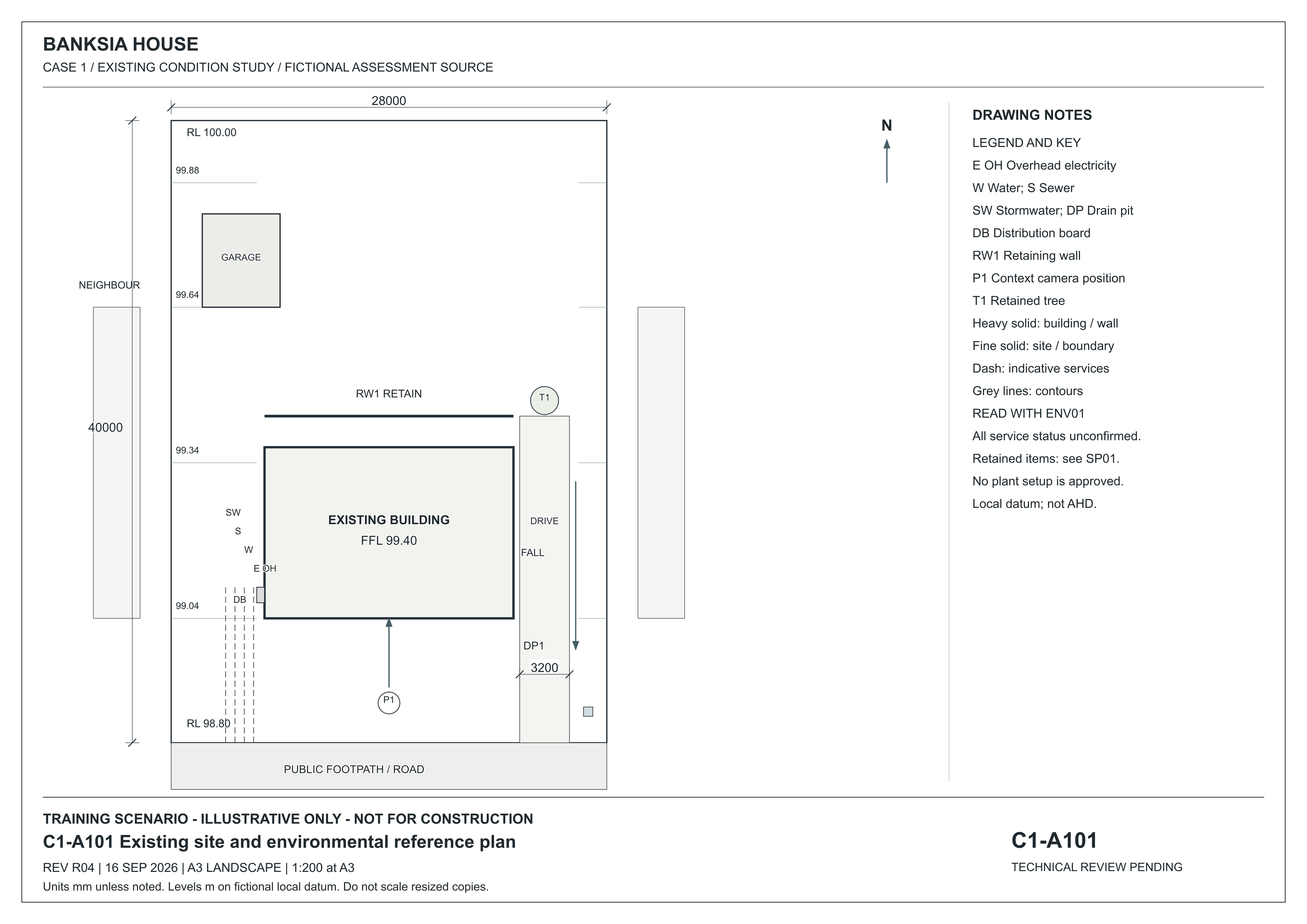
Existing site and environmental reference plan
CONTROLLED FICTIONAL TRAINING RESOURCE Use the record and its stated limitation. Do not infer hidden support, services or approvals from the image alone.
C1-A101 R04 – Existing site and environmental reference plan. North-up site reference with building, neighbouring interfaces, rear-to-front levels, indicative services, retained wall and drainage pit. Dimensions and levels are stipulated fictional inputs. Reproduced in this guide at reduced size; use written dimensions, not a ruler on this page.
Use the record and its stated limitation. Do not infer hidden support, services or approvals from the image alone.
This visual is draft case-study teaching material. Reading it is not an inspection, a measurement or evidence of performance.
Banksia House building context
CONTROLLED FICTIONAL TRAINING RESOURCE Use the record and its stated limitation. Do not infer hidden support, services or approvals from the image alone.
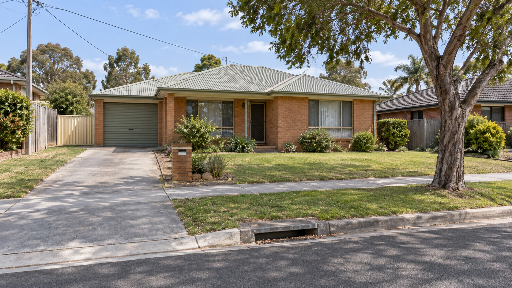
C1-P01 R04 – Banksia House building context. Brick veneer over timber framing; timber roof trusses; metal roof; concrete slab on ground. Exterior appearance reference only; use the controlled drawings for dimensions and concealed construction. Reproduced in this guide at reduced size; use written dimensions, not a ruler on this page.
Use the record and its stated limitation. Do not infer hidden support, services or approvals from the image alone.
This visual is draft case-study teaching material. Reading it is not an inspection, a measurement or evidence of performance.
Existing site and environmental reference plan
CONTROLLED FICTIONAL TRAINING RESOURCE Use with the nominated calculation model and records; an image is not engineering confirmation or permission to act.
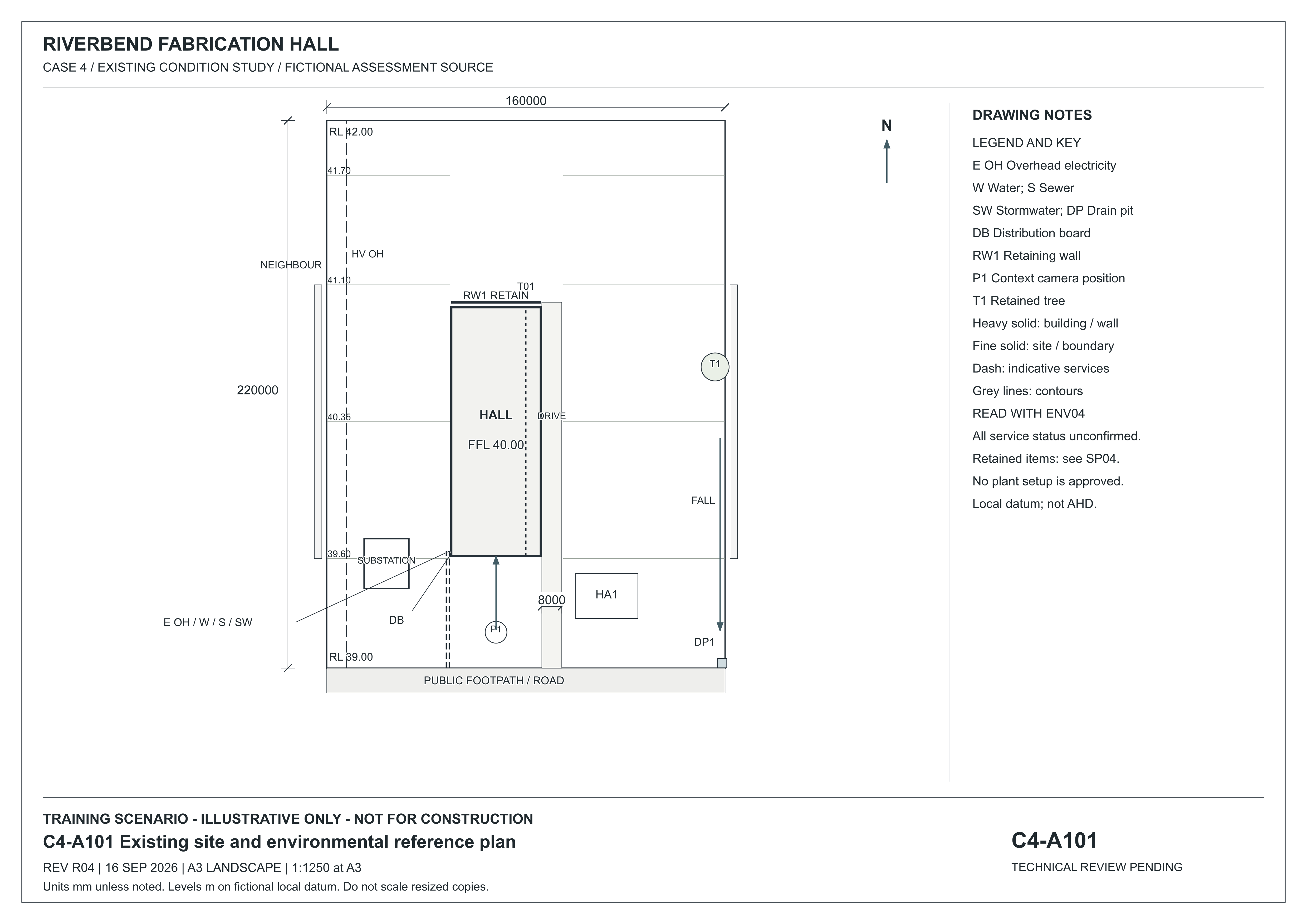
C4-A101 R04 – Existing site and environmental reference plan. North-up site reference with building, neighbouring interfaces, rear-to-front levels, indicative services, retained wall and drainage pit. Dimensions and levels are stipulated fictional inputs. Reproduced in this guide at reduced size; use written dimensions, not a ruler on this page.
Use with the nominated calculation model and records; an image is not engineering confirmation or permission to act.
This visual is draft case-study teaching material. Reading it is not an inspection, a measurement or evidence of performance.
Riverbend Fabrication Hall building context
CONTROLLED FICTIONAL TRAINING RESOURCE Use with the nominated calculation model and records; an image is not engineering confirmation or permission to act.
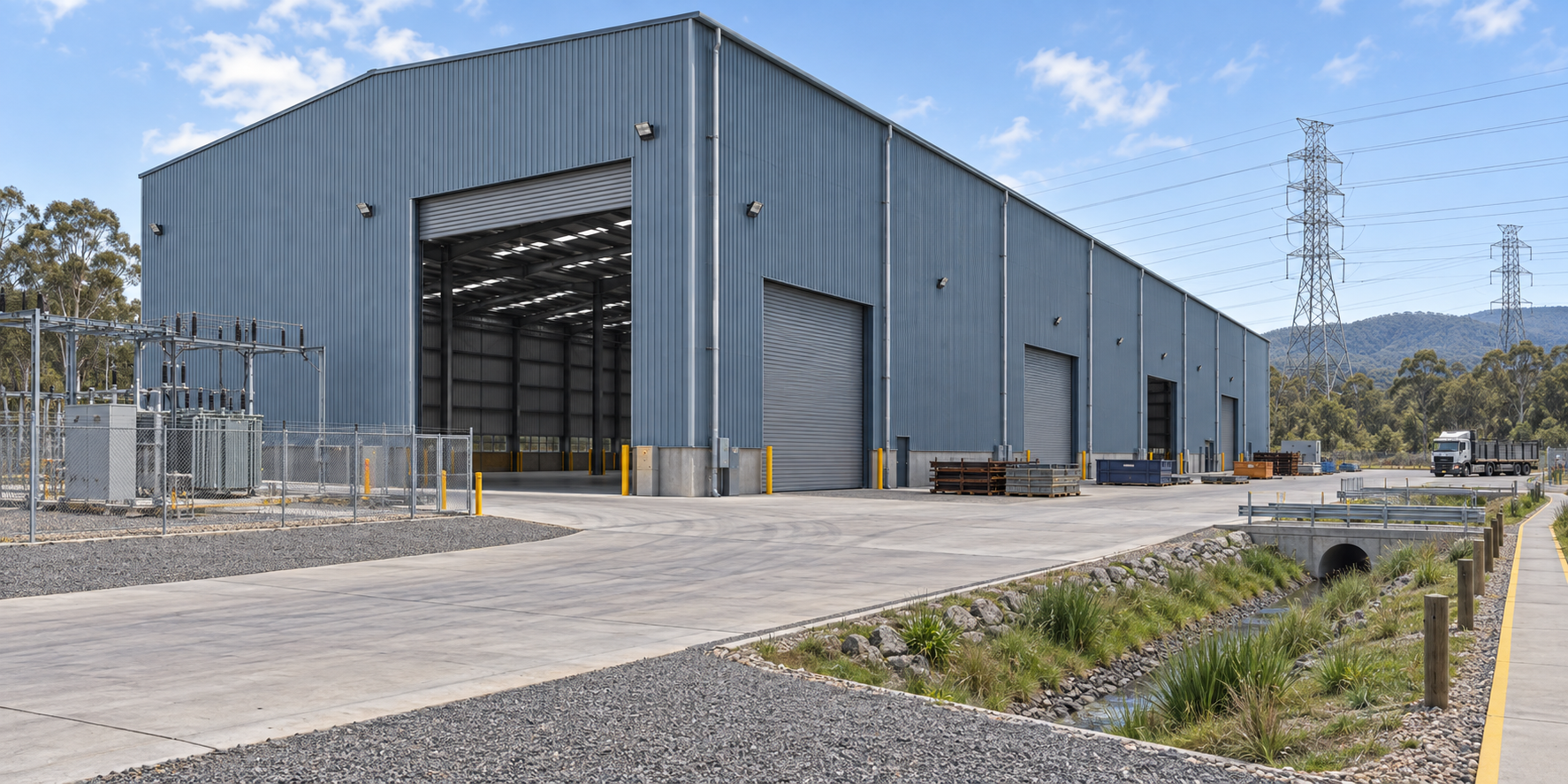
C4-P01 R04 – Riverbend Fabrication Hall building context. Eleven steel portal frames at 10 m centres; metal cladding on purlins and girts; ground slab; independent office mezzanine; overhead crane runway. Exterior appearance reference only; use the controlled drawings for dimensions and concealed construction. Reproduced in this guide at reduced size; use written dimensions, not a ruler on this page.
Use with the nominated calculation model and records; an image is not engineering confirmation or permission to act.
This visual is draft case-study teaching material. Reading it is not an inspection, a measurement or evidence of performance.
Drawings and written requirements work together
A drawing locates and represents information; a specification can describe requirements that cannot sensibly be drawn in full. These may concern material properties, workmanship, tolerances, finishes, inspections, protection and performance. A schedule can connect a code on the drawing to those written requirements. Reading only the geometry can therefore miss an important condition.
A tolerance is an allowed variation around a specified value or arrangement. It is not permission to invent a dimension where none is supplied. A material grade or product designation conveys a defined property or specification; it cannot be inferred solely from appearance. A note requiring retained finishes to be protected can affect access, dust control and the selected process. This can happen even when the note does not change the demolition outline.
Specifications may also identify interfaces with specialist work or nominated parties. That information helps coordinate who supplies a report, confirms a service condition or accepts a temporary arrangement. It does not remove the need to verify that the required information has actually been provided and applies to the current stage.
Where two documents conflict, use the project's controlled clarification process and any formally established document precedence. Do not invent a universal rule that drawings always override text, or that the latest date automatically wins. For example, a plan may show removal to a boundary while a written requirement preserves a weatherproof junction at that same boundary. The conflict needs a coordinated resolution explaining the intended final and temporary conditions, not a field compromise hidden from the document owner.
A missing detail at a retained roof junction
A demolition package for a single-storey annex illustrates how a missing reference can affect several decisions. The site plan locates the annex beside a retained building and an access lane. The floor plan identifies the removal boundary. An elevation distinguishes the annex roof from the higher retained façade. A section shows that the two roof lines meet at different levels. The structural detail needed to explain that junction is referenced but not included in the pack.
The drawings establish the location, intended boundary and different roof levels. They do not establish the supporting and weatherproofing relationship at the junction. The lower roof therefore cannot be assumed independent from these views.
The resulting request for information identifies the drawing numbers and revisions, the location, the missing reference and the decision it affects. It asks for the necessary clarification without supplying an improvised structural answer. Photographs or observations may support the question only when obtained through authorised safe access and clearly labelled as observations rather than concealed-condition proof.
Interpreting a control record
A control record for a material-transfer area needs to identify the activity, location, revision and intended use. These details establish whether the document applies to the work. Its supporting information and unresolved assumptions are equally important: changing a heading does not make an unrelated record applicable.
A hazard entry must explain the route to harm. Terms such as plant or debris identify a subject but not the exposure. The record needs to establish how movement or material could reach workers, visitors, neighbouring property or an environmental receptor. Deliveries and changing work areas can alter those pathways.
The control entry distinguishes measures that are proposed from those already implemented. It identifies how each measure reduces exposure, who establishes and maintains it, and what technical information it depends on. Exclusion distances and load limits require the relevant site-specific basis; they cannot be derived from a generic form.
Verification must address the condition being relied upon. A photograph may establish the location of a sign, but it cannot establish the capacity of a structural support. A signature may record acknowledgement without verifying the assumptions behind the arrangement.
If a delivery blocks the planned route, the review must address the changed movement and exposure. The revised arrangement must be communicated and obsolete instructions withdrawn from use. Traffic arrangements, the demolition work plan, relevant safe work method statements, emergency access and briefings must remain consistent. A permit authorises a defined activity under specified conditions; it does not replace unrelated technical confirmations.
Demolition training at OnShift
The fieldbook is free to read. If you are working towards a supervisor role, these are the training pages that cover the same ground.