
Legends, symbols, abbreviations, scale, levels and dimensions
Drawing conventions define what lines and symbols mean. Scale, dimensions, levels and consistent units allow geometric calculations, while the measurement basis limits what those results establish.
Legends, symbols and abbreviations
A legend explains the symbols, line types, hatching and other conventions used in a drawing or package. A dashed line may represent something hidden, overhead, existing or otherwise distinguished, depending on that convention. A hatch may identify a material or an extent of work. Never assign a meaning solely because another project's drawing used the same pattern.
Symbols can represent section cuts, detail references, levels, doors, services or other features. Their direction and associated labels matter. A section arrow indicates the direction of view; its reference tells the reader where the corresponding section is found. A detail bubble identifies another view; without that view, it does not establish the junction's construction.
Abbreviations also depend on context. FFL commonly means finished floor level, while a structural slab level may be identified differently. NTS commonly means not to scale. RL often identifies a reduced level referenced to a datum. These familiar expansions are starting points to check against the actual legend and notes, not a promise that every author uses identical abbreviations.
Colour alone is fragile information. A drawing may be printed in black and white, copied at low quality or viewed on a small screen. The removal boundary should be understood through the complete issued convention, including labels and notes. If reproduction makes a critical distinction illegible, obtain a usable controlled copy. Guessing from a faint line is not a reasonable substitute for information needed to protect a retained element.
Technical terms
Hazard — A source or situation with potential to cause harm.
Risk — The possibility of harm, considered with its likelihood and consequence in context.
Exposure — The opportunity for a person or receptor to come into contact with a hazard.
Consequence — The harm or loss that could result.
Control — A measure that eliminates or reduces risk.
Remaining risk — Risk considered after the specified controls have actually been applied.
Elimination — Removing the hazard or hazardous exposure from the work.
Substitution — Replacing a hazard with a less hazardous alternative.
Isolation — Separating people from a hazard.
Engineering control — A physical or designed measure that acts on a hazard or exposure pathway.
Administrative control — An arrangement such as procedures, scheduling, information or supervision.
PPE — Personal protective equipment.
RPE — Respiratory protective equipment.
SWMS — Safe work method statement; a document for relevant high-risk construction work.
DWP — Demolition work plan.
Permit — A bounded authorisation within a defined control system, not universal proof of safety.
Induction — Introduction to relevant site conditions, responsibilities and arrangements.
Pre-start — A check or briefing before work or equipment use; distinct from scheduled servicing.
Verification — Checking evidence that the required condition or control exists and works as intended.
Consultation — Sharing relevant information, hearing affected workers' views and considering them in decisions.
Load path — The connected route by which forces pass through a structure to its supports.
Compression — A pushing action within a material or member.
Tension — A pulling action within a material or member.
Bending — A response to loading that tends to curve a member.
Shear — Action tending to make parts move past one another.
Temporary works — Engineered or other temporary arrangements supporting construction or demolition needs; specialist design and control may be required.
Respirable dust — Particles small enough to reach deep into the lungs.
LEL — Lower explosive limit; the lowest flammable gas or vapour concentration in air at which flame can propagate under the relevant conditions. Percentage of LEL is not percentage gas concentration or a safe-breathing decision.
Receptor — The person, property or environmental feature potentially affected.
Change control — The process of recognising a change, reviewing affected assumptions and controls, and communicating the revised arrangement.
Air monitoring — Competently planned measurement of airborne contaminants to assess exposure and control effectiveness.
Health monitoring — Medical monitoring for health effects, carried out or supervised by an appropriately experienced doctor when required.
Reading a drawing legend
LEARNING AID A generic learning aid explains a principle. It does not establish a project fact, hidden condition, capacity, approval or work release.
 Open full-size illustration
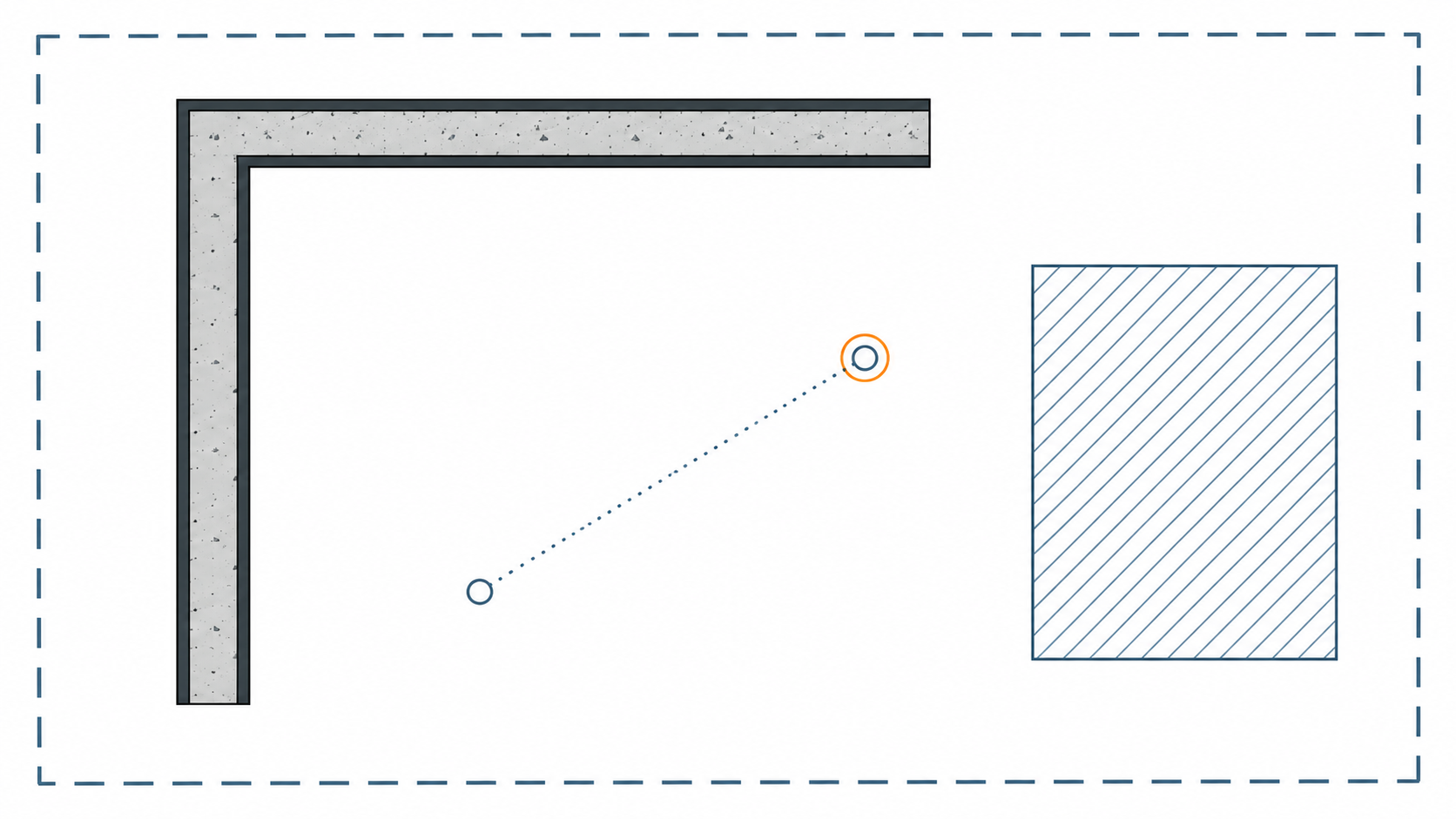
Heavy outlines, a dashed perimeter, diagonal hatch and a dotted line with circular marks are visibly different conventions. This example does not assign them universal meanings. Find the legend and notes belonging to the actual drawing.
A generic learning aid explains a principle. It does not establish a project fact, hidden condition, capacity, approval or work release.
This visual is draft case-study teaching material. Reading it is not an inspection, a measurement or evidence of performance.
Scale is a ratio, not a guarantee of print accuracy
A scale of one to fifty expresses a relationship between the correctly reproduced drawing and the depicted object. One unit measured on that drawing represents fifty of the same units in the object. For example, forty-two millimetres on a drawing at one to fifty represents two thousand one hundred millimetres, or two point one metres. Multiply the drawing measurement by the scale factor, then convert units deliberately.
That calculation is only as reliable as the reproduction and the information being measured. A file printed using fit to page can change the paper scale. A screenshot can be resized. A drawing can contain details at different scales. A scale note in the title block does not establish that every detail, image or printed copy has that scale.
Written dimensions and the drawing's specific instructions control dimensional interpretation; scaling is not a way to overrule them. Where a required dimension is missing or conflicts with another value, obtain clarification through the controlled process. A graphical scale can help reveal reproduction changes when reproduced with the drawing. But it does not resolve an unclear feature, a distorted scan or an explicit instruction not to scale.
A measurement's basis determines what it can establish. An estimate taken by scaling a verified reproduction is different from an issued written dimension, and both are different from a properly obtained site measurement. Recording that distinction prevents a rough quantity estimate from acquiring the appearance of a precise construction or demolition instruction. This matters when the estimate is copied into another document.
Plan, elevation and section
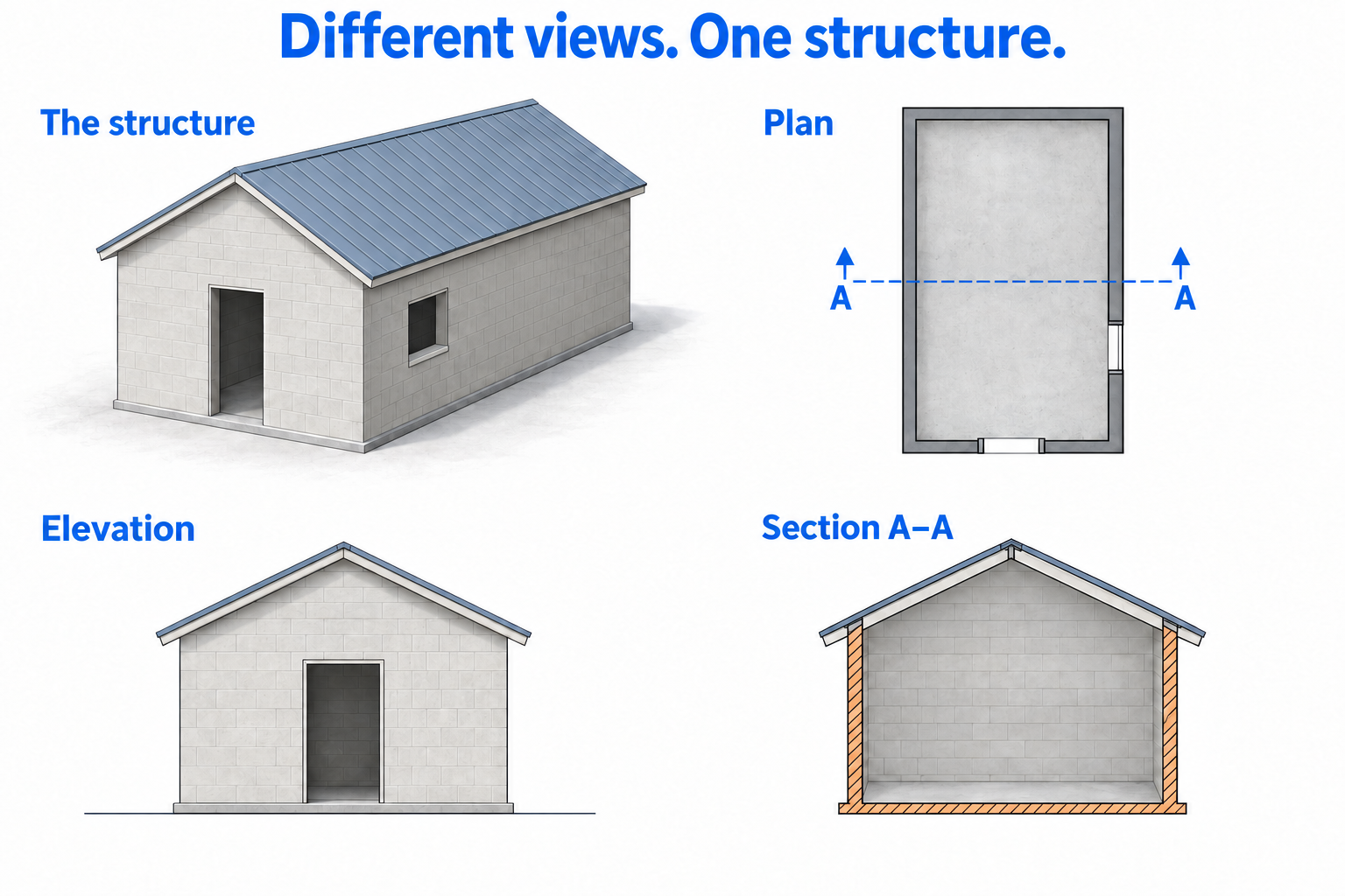
Drawing views describe different spatial relationships within the same structure.
 Open full-size illustration
A plan shows the horizontal arrangement viewed from above. An elevation shows the vertical outline of an external face. A section represents a cut through the structure, revealing internal relationships between elements such as roofs, walls and floors.
Drawing references connect these views to orientation, levels, dimensions and details. A plan may locate a connection without establishing its height; an elevation may show its external position without revealing a concealed arrangement. A missing referenced section or detail leaves an information gap.
The illustrated views are not to scale. Apparent line thickness cannot establish structural support, and dimensions cannot be measured from these shapes. On an actual drawing, interpretation depends on the project identity, revision, issue purpose, legend, units and applicable notes.
Units, endpoints and dimension chains
A dimension connects defined points. It may describe an overall length, a centre-to-centre spacing, a clear opening, a finished face or a structural face. Two values can look inconsistent because they measure different endpoints. A centre-to-centre dimension includes portions of the adjoining members, so member widths and connection details can reduce the clear opening. Before adding or subtracting dimensions, identify exactly what each extension line, note or label refers to.
A chain of smaller dimensions can help explain an overall length, but rounding, omitted elements and different reference faces may affect the comparison. A mismatch is a reason to investigate, not permission to distribute the difference across the work. Written dimensional information must be read with the relevant details and notes.
Units deserve explicit attention. One metre contains one thousand millimetres. A dimension of two thousand four hundred millimetres is two point four metres. Area and volume use squared and cubed units, so their conversions cannot be treated as ordinary length conversions. A calculation that multiplies metres by millimetres without conversion can produce a plausible-looking number with the wrong unit and magnitude.
For example, a rectangular face is described as six metres long and two thousand five hundred millimetres high. For an area calculation, that height is two point five metres. Six multiplied by two point five is fifteen square metres. That result is a geometric area only. It says nothing about the wall's mass, support function, contamination or removal method. Naming the endpoints, units and purpose keeps a useful measurement within the limits of what it actually establishes.
A-A longitudinal section
CONTROLLED FICTIONAL TRAINING RESOURCE Use with the nominated calculation model and records; an image is not engineering confirmation or permission to act.
 Open full-size illustration
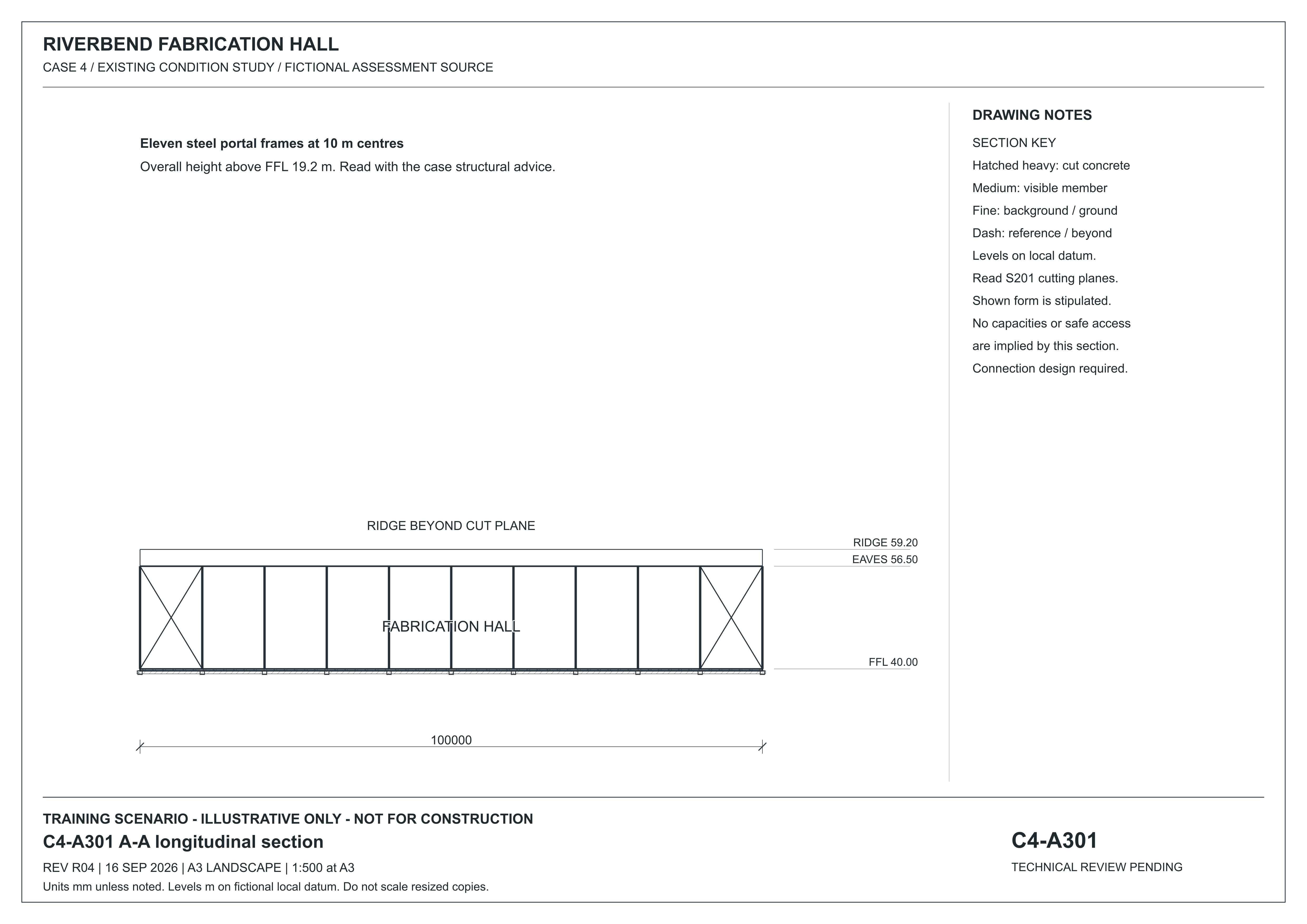
C4-A301 R04 – A-A longitudinal section. A-A longitudinal section of Riverbend Fabrication Hall, identifying floor, eaves and ridge levels and the stated structural system. Local datum, not an engineering design. Reproduced in this guide at reduced size; use written dimensions, not a ruler on this page.
Use with the nominated calculation model and records; an image is not engineering confirmation or permission to act.
This visual is draft case-study teaching material. Reading it is not an inspection, a measurement or evidence of performance.
Area and solid volume
Area describes a surface; volume describes three-dimensional space. For a rectangle, multiply length by width. For a rectangular prism, multiply that area by thickness or height. Use consistent units throughout. Irregular shapes can sometimes be divided into simpler shapes for an estimate, but the chosen simplification and any omitted features must be recorded.
For example, a uniformly solid slab measures seven point two metres by four point five metres. Its stated thickness is zero point one five metres. Its plan area is seven point two multiplied by four point five, which equals thirty-two point four square metres. Multiplying that area by zero point one five gives four point eight six cubic metres of solid geometric volume.
Suppose the same slab has a full-depth rectangular opening measuring one point two metres by zero point eight metres. The opening area is zero point nine six square metres. The net area becomes thirty-one point four four square metres. At the stated uniform thickness, the net solid volume is four point seven one six cubic metres. The subtraction is valid because the opening extends through the slab's full depth and the thickness is uniform.
Real slabs may have beams, thickened edges, voids, toppings, reinforcement and uncertain thickness. The calculated intact volume does not establish loose waste volume, actual mass or a floor's loading capacity. Loose material contains spaces between fragments, so its packing differs from the solid geometry. The dimensions used in a quantity estimate also need confirmation against the actual construction.
Levels locate height relative to a reference
A level is a vertical position relative to a stated datum. A datum may be a recognised survey reference or a project-specific reference. A value by itself does not tell the reader which reference is being used. Grid references locate positions in plan, while levels locate them vertically; the two systems work together to identify a place in three dimensions.
Finished floor level describes a finished surface when that is the package's defined convention. Structural slab level refers to a structural surface under the relevant convention. Their difference can represent finishes or other build-up, but it must not be invented where the documents do not establish it. A level attached to an arrow also needs its exact physical reference point understood.
For example, use one consistent datum for two surfaces. One is at level twelve point eight five metres; the other is at twelve point three zero metres. They differ by zero point five five metres, or five hundred and fifty millimetres. Subtracting the lower value from the higher gives the difference. The result does not explain what construction lies between the surfaces or whether either surface can support plant.
Keep sign, datum and orientation visible in reasoning. Below a datum may be shown with a negative value. A level from an unrelated datum cannot be combined merely because both values use metres. When a drawing and site information disagree, preserve the discrepancy and obtain the required survey or design clarification. Subtracting levels is meaningful only when the datum, physical reference points and units are comparable.
B-B transverse section
CONTROLLED FICTIONAL TRAINING RESOURCE Use the record and its stated limitation. Do not infer hidden support, services or approvals from the image alone.
 Open full-size illustration
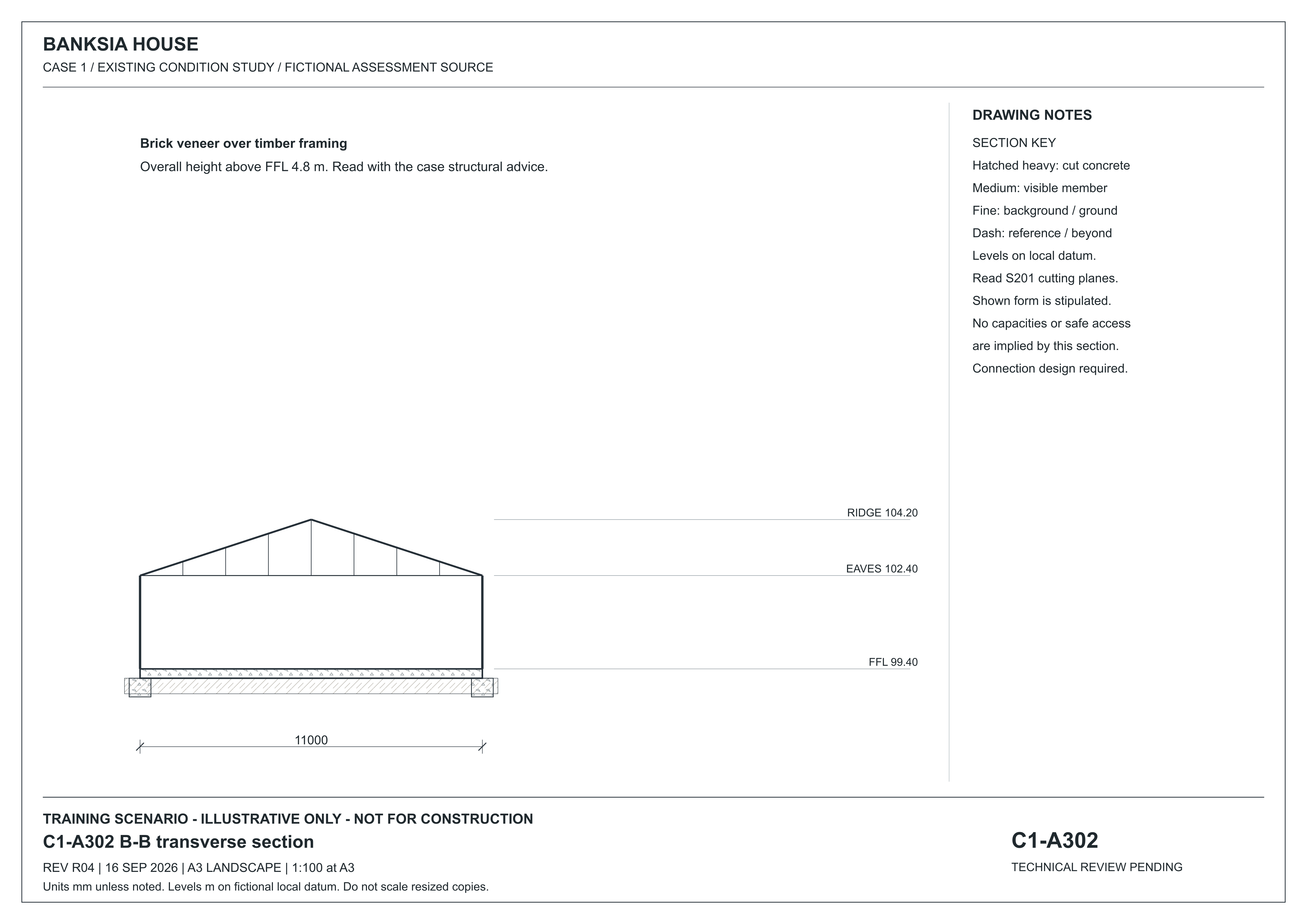
C1-A302 R04 – B-B transverse section. B-B transverse section of Banksia House, identifying floor, eaves and ridge levels and the stated structural system. Local datum, not an engineering design. Reproduced in this guide at reduced size; use written dimensions, not a ruler on this page.
Use the record and its stated limitation. Do not infer hidden support, services or approvals from the image alone.
This visual is draft case-study teaching material. Reading it is not an inspection, a measurement or evidence of performance.