Skip to reading
    Book overview
    THE DEMOLITION SUPERVISOR’S FIELDBOOK / CHAPTER 42
    Part VI · Plans, structures and engineering interface

    Structural systems and load paths

    Gravity and lateral forces pass through members, connections and foundations. Demolition changes those load paths and the restraints that keep the remaining structure stable.

    A load path is a continuous route for force

    A load path describes how force travels through a structure to its supports and ultimately the ground. A load does not disappear when it reaches a beam or column. That member must transfer its action through a connection into the next part of the system. The route is only as dependable as the components and connections required to complete it.

    In a simplified roof example, roofing loads may pass to purlins, then to rafters or trusses, then to columns or walls, then through footings into the ground. A floor can have a different arrangement: a slab may span to beams, or it may transfer load directly to columns or walls. The actual system must be established from the relevant evidence, not selected from this example by resemblance.

    Loads include the structure's own weight and other actions. Permanent elements contribute dead load. Occupants, stored items and use of the building contribute imposed loads. Demolition can introduce debris, machines, temporary equipment and applied forces outside the original use assumptions. Water and weather can also alter loading conditions.

    Identifying a large beam does not establish a complete load path. Its force must pass through connections and supports into the rest of the structure and the ground. An unknown connection leaves a gap in the structural information, even when the adjoining members are visible.

    The four cases show why an external appearance is not a complete load path. Banksia's controlled exercise records stipulate brick veneer over timber framing. Cronulla combines real source information with a separately stipulated construction model. Riverbend stipulates a steel industrial system. Their different evidence bases must remain visible when explaining the structure.

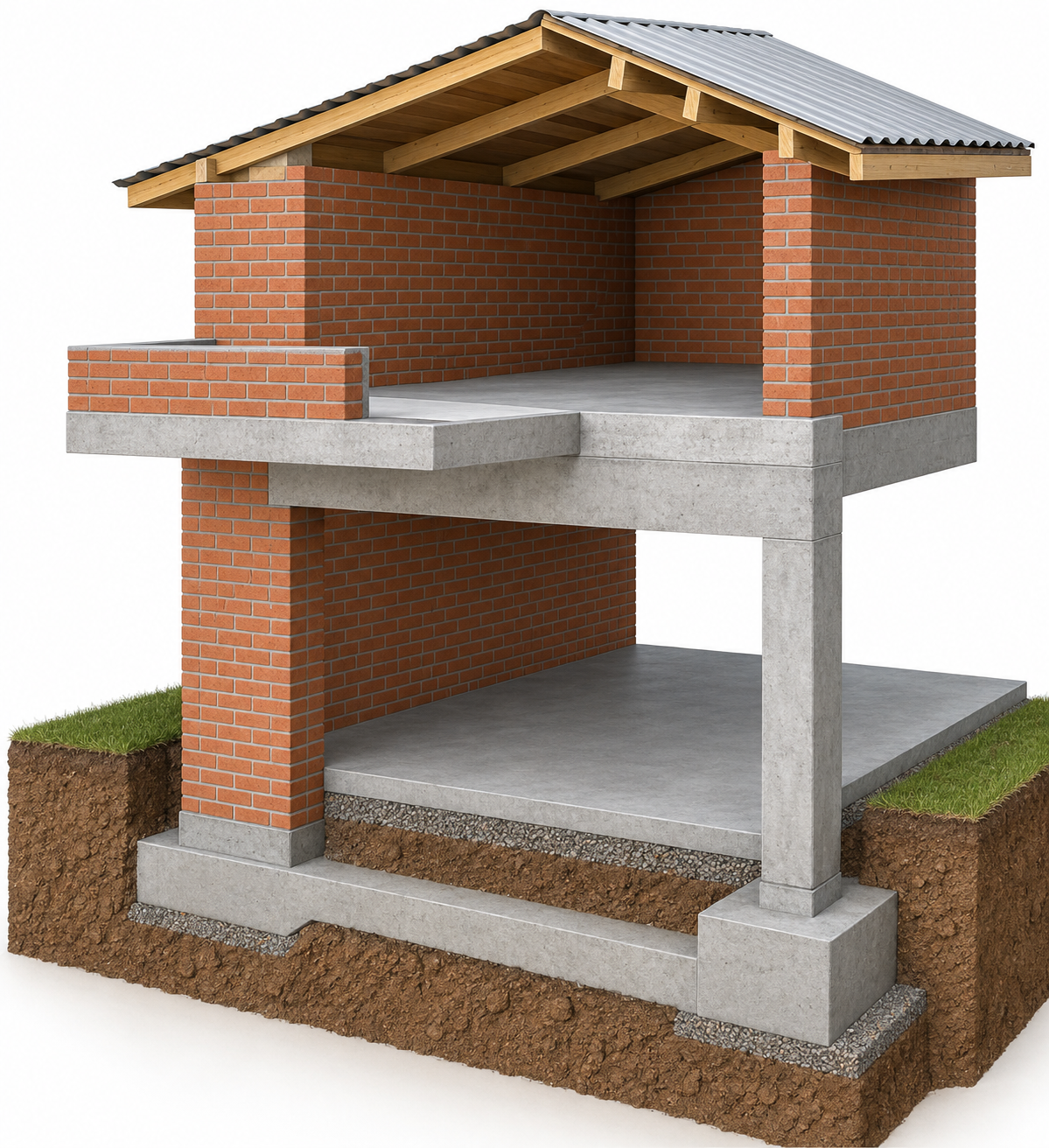
    LA-01 is a generic representative support bay, not a measured Cronulla section. Follow the illustrated floor, beam and supports to the ground. Then identify which part of a case explanation comes from its construction statement and which connection remains unverified. A believable route for force is a hypothesis until the required evidence supports it.

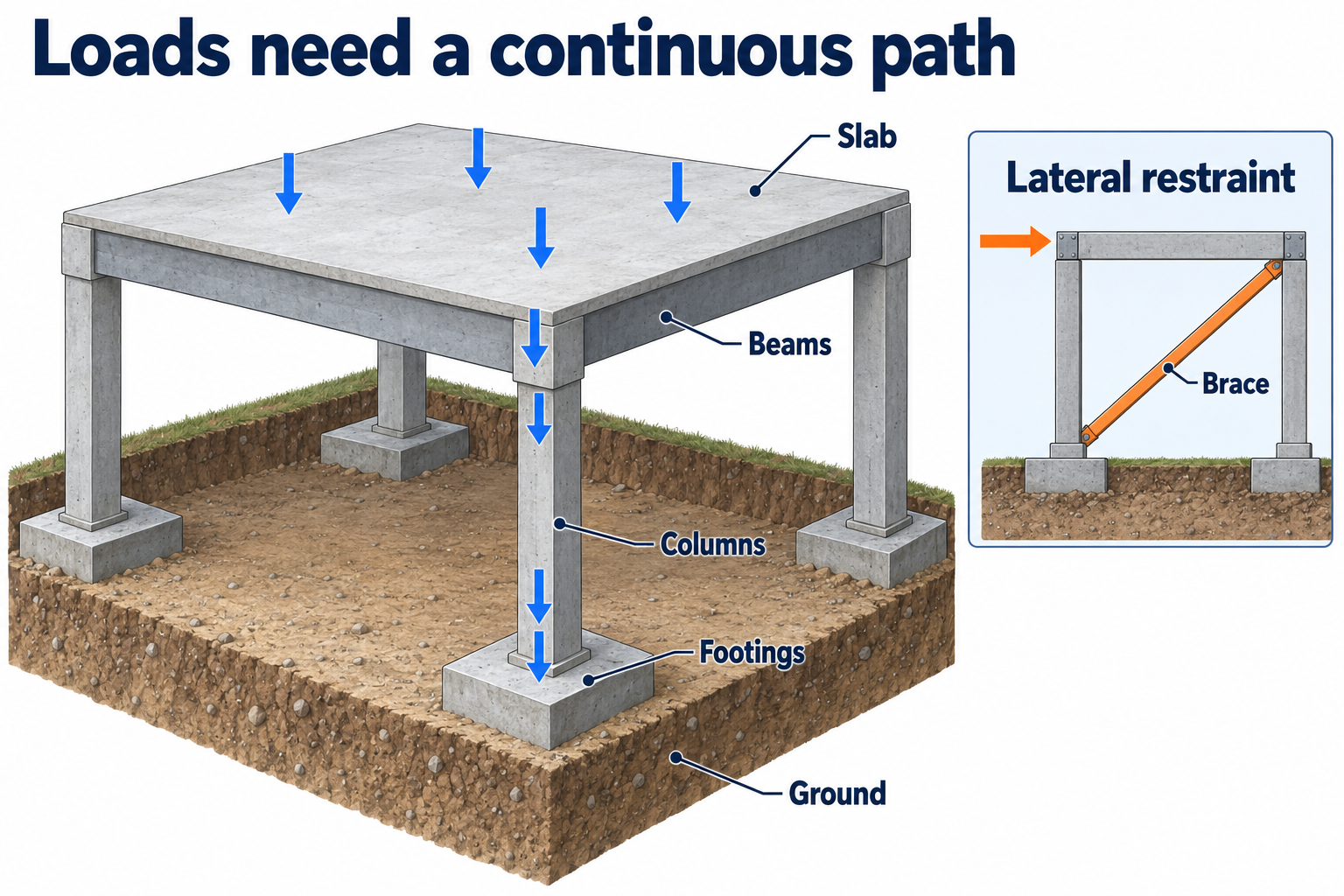
    Gravity loads and lateral stabilityA concrete slab rests on beams supported by columns and pad footings in the ground. Blue arrows show downward load transfer. A separate inset identifies an orange diagonal brace providing lateral restraint. No capacities or removal sequence are specified.Open full-size illustration

    Roof and floor loads pass through supporting beams or walls, then through columns or walls, into foundations and the ground. Each connection in the vertical chain represents a dependency: the receiving element must transfer the relevant action to the next support.

    Lateral actions involve a different but connected set of relationships. Bracing, connections and restraints limit unwanted movement. An element that carries little gravity load can still provide essential lateral stability. Removing it may change the behaviour of the structure that remains.

    Demolition alters loads, connections and restraints as work progresses. The partly dismantled structure must therefore be considered at each stage, using the current engineering information. Hidden construction, deterioration, ground conditions and temporary works may affect the assessment.

    The schematic identifies load-transfer relationships, not member capacities or a removal sequence. Stage-specific structural decisions require information about the actual elements, their condition and their connections. An unresolved load path requires technical review.

    Case visual LA-01: Generic representative support bay, showing masonry, a concrete transfer beam…

    LEARNING AID A teaching aid may illustrate a principle but does not establish a project fact, capacity, condition, authority approval or work release.

    Learning aid: Generic representative support bay, showing masonry, a concrete transfer beam and supports; this is not a complete building or measured Cronulla sectionOpen full-size illustration

    Generic representative support bay, showing masonry, a concrete transfer beam and supports; this is not a complete building or measured Cronulla section

    A teaching aid may illustrate a principle but does not establish a project fact, capacity, condition, authority approval or work release.

    This visual is draft case-study teaching material. Reading it is not an inspection, a measurement or evidence of performance.

    Buildings must resist sideways actions as well as weight

    Gravity acts vertically, but buildings also experience lateral actions such as wind. A lateral-load system transfers those forces through a combination of surfaces, frames, bracing, walls, connections and foundations. Uplift can also reverse the direction in which some connections must act. A detail that supports downward bearing may not by itself provide an adequate tie against uplift.

    A diaphragm is a floor or roof system that transfers forces within its plane to the vertical resisting elements. Its effectiveness depends on its construction and connections. A braced frame uses members arranged to resist lateral movement through defined force paths. A moment-resisting frame relies on the bending resistance of its members and joints. A shear wall provides resistance to lateral forces through its wall system and supporting connections.

    Restraint is related to, but not identical with, carrying the main vertical load. A small tie, brace or connected surface may prevent a member from moving sideways or twisting. Removing it can reduce stability even if it carries little obvious gravity load. This is why apparently lightweight cladding, roof elements or cross-members cannot automatically be dismissed as structurally irrelevant.

    For example, a long member can resist loading in its principal direction while depending on intermediate restraint to avoid sideways movement. Taking away the restraint changes the member's behaviour without changing its visible cross-section. Strength and stability depend on the assembled system. The demolition sequence must account for how the lateral system and individual restraints remain effective in each temporary condition.

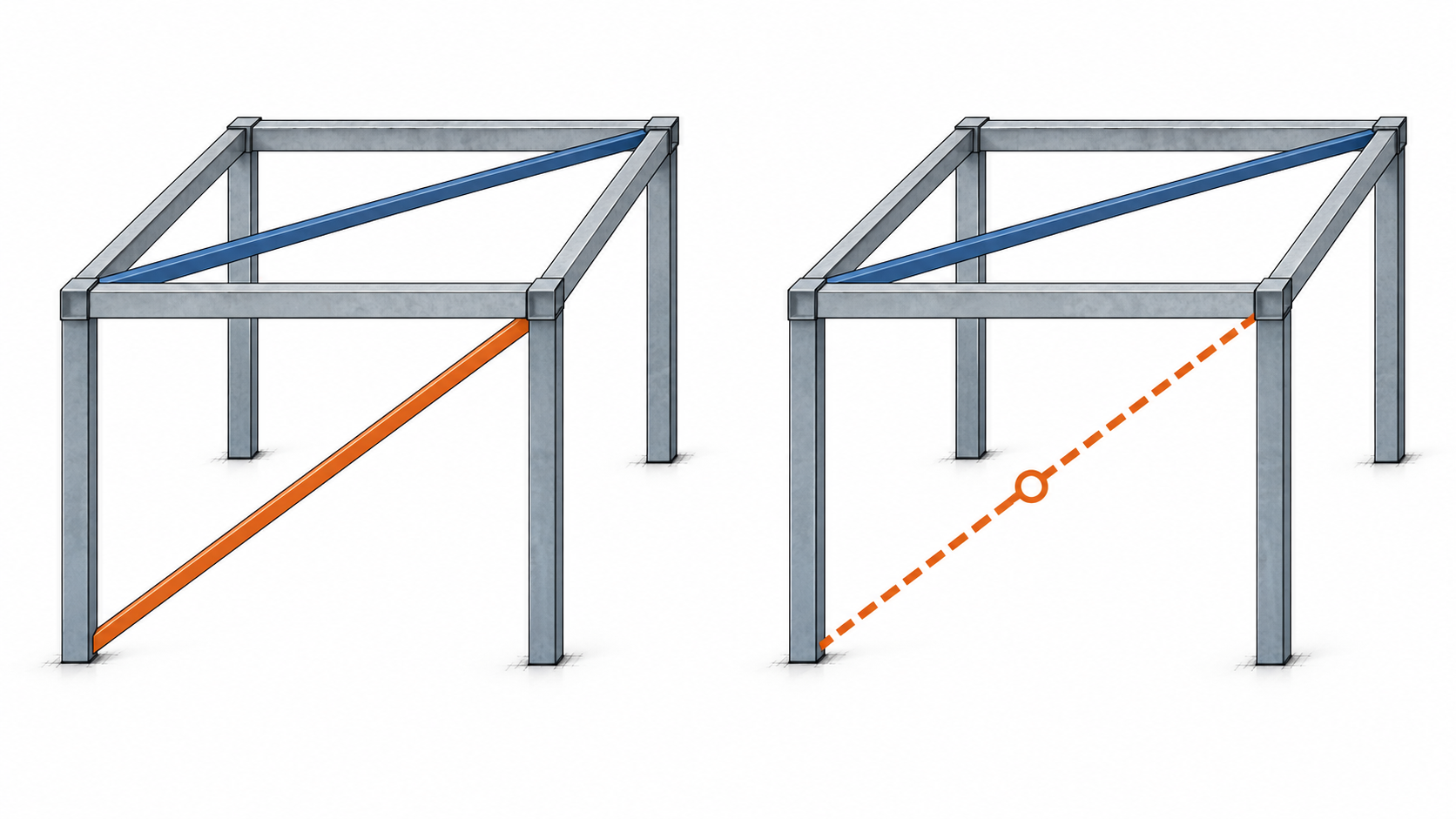
    Case visual LA-12: Both frames show a roof-plane diagonal

    LEARNING AID A generic learning aid explains a principle. It does not establish a project fact, hidden condition, capacity, approval or work release.

    Two matching open frames, each with a roof diagonal; the left has a solid front-wall diagonal and the right a dashed outline of that same diagonal.Open full-size illustration

    Both frames show a roof-plane diagonal. The left frame also shows a diagonal within the front wall plane. On the right, its dashed former position marks a changed restraint relationship. This partial model does not establish that either frame is stable or adequately braced.

    A generic learning aid explains a principle. It does not establish a project fact, hidden condition, capacity, approval or work release.

    This visual is draft case-study teaching material. Reading it is not an inspection, a measurement or evidence of performance.

    Structural systems and their interfaces

    In a load-bearing wall system, walls carry specified loads to the foundations. In a framed system, beams and columns may carry much of the gravity load while separate bracing or walls provide lateral resistance. A building can combine these systems, and a wall that is not a main gravity support can still contribute restraint, fire separation or enclosure. Labels must be supported by the actual design and condition.

    Precast construction uses manufactured elements assembled through bearings, joints and connections. The connection details are central to the complete system. A panel's large mass does not explain how it is restrained out of plane or how it remains stable at an intermediate stage. Temporary erection assumptions and later alterations may be relevant when the building is dismantled.

    Composite construction combines materials so that they act together, such as a steel member connected to a concrete floor. Their combined action depends on the intended connections and material condition. Separating part of the assembly can remove behaviour that was available in the completed structure. Similarly, an infill wall can influence a frame's stiffness even where it was not treated as the principal load-bearing system.

    A transfer structure redirects loads from one arrangement of supports to another, for example where upper columns do not continue directly to the ground. This creates dependencies that are not obvious from one floor plan. Repeated room layouts and visible column lines are not enough to rule them out. Read sections, structural drawings and reports together, and retain uncertainty where the supporting arrangement has not been established.

    Technical terms

    Hazard — A source or situation with potential to cause harm.

    Risk — The possibility of harm, considered with its likelihood and consequence in context.

    Exposure — The opportunity for a person or receptor to come into contact with a hazard.

    Consequence — The harm or loss that could result.

    Control — A measure that eliminates or reduces risk.

    Remaining risk — Risk considered after the specified controls have actually been applied.

    Elimination — Removing the hazard or hazardous exposure from the work.

    Substitution — Replacing a hazard with a less hazardous alternative.

    Isolation — Separating people from a hazard.

    Engineering control — A physical or designed measure that acts on a hazard or exposure pathway.

    Administrative control — An arrangement such as procedures, scheduling, information or supervision.

    PPE — Personal protective equipment.

    RPE — Respiratory protective equipment.

    SWMS — Safe work method statement; a document for relevant high-risk construction work.

    DWP — Demolition work plan.

    Permit — A bounded authorisation within a defined control system, not universal proof of safety.

    Induction — Introduction to relevant site conditions, responsibilities and arrangements.

    Pre-start — A check or briefing before work or equipment use; distinct from scheduled servicing.

    Verification — Checking evidence that the required condition or control exists and works as intended.

    Consultation — Sharing relevant information, hearing affected workers' views and considering them in decisions.

    Load path — The connected route by which forces pass through a structure to its supports.

    Compression — A pushing action within a material or member.

    Tension — A pulling action within a material or member.

    Bending — A response to loading that tends to curve a member.

    Shear — Action tending to make parts move past one another.

    Temporary works — Engineered or other temporary arrangements supporting construction or demolition needs; specialist design and control may be required.

    Respirable dust — Particles small enough to reach deep into the lungs.

    LEL — Lower explosive limit; the lowest flammable gas or vapour concentration in air at which flame can propagate under the relevant conditions. Percentage of LEL is not percentage gas concentration or a safe-breathing decision.

    Receptor — The person, property or environmental feature potentially affected.

    Change control — The process of recognising a change, reviewing affected assumptions and controls, and communicating the revised arrangement.

    Air monitoring — Competently planned measurement of airborne contaminants to assess exposure and control effectiveness.

    Health monitoring — Medical monitoring for health effects, carried out or supervised by an appropriately experienced doctor when required.

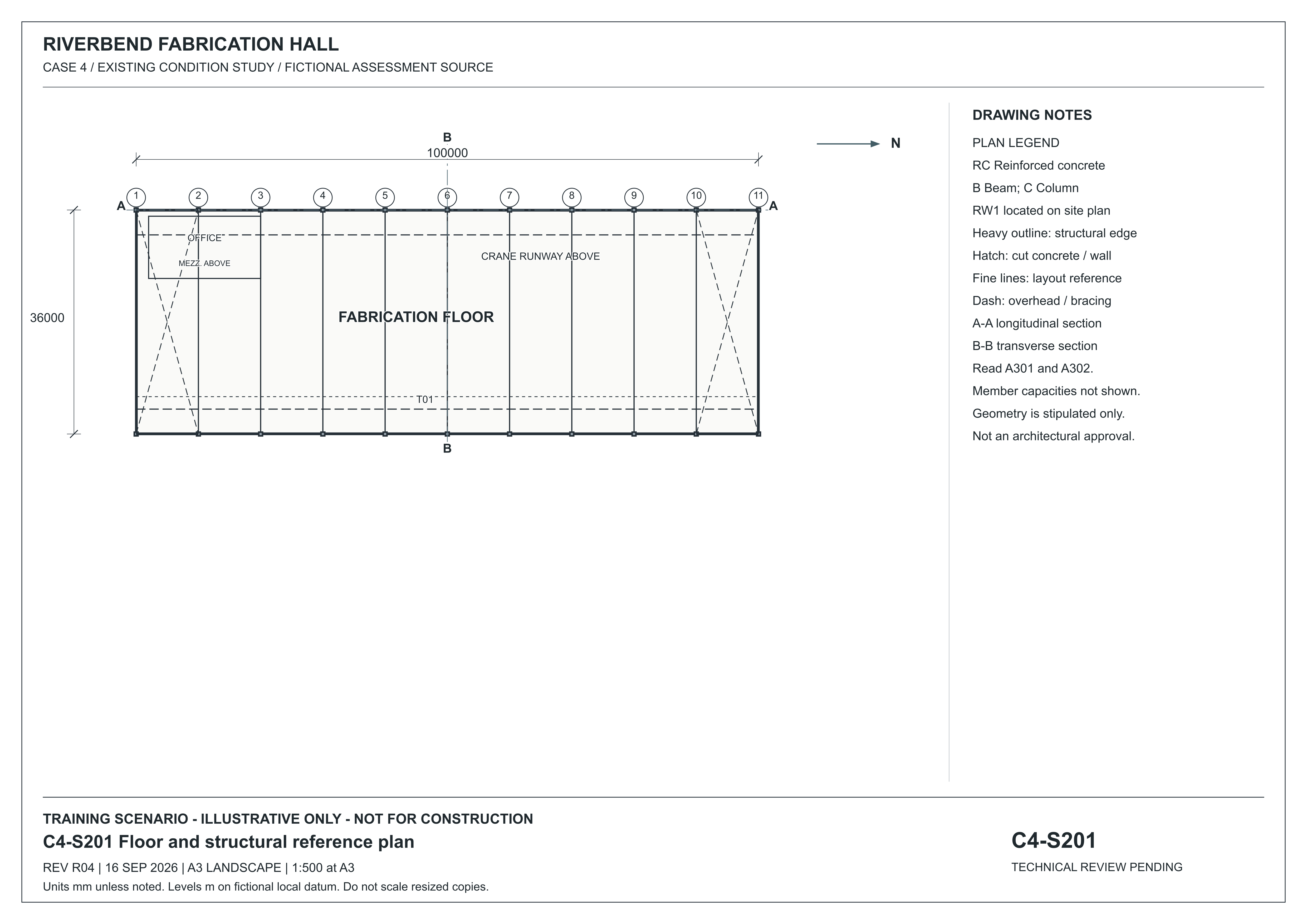
    Case visual C4-S201-R04: Floor and structural reference plan

    CONTROLLED FICTIONAL TRAINING RESOURCE Use with the nominated calculation model and records; an image is not engineering confirmation or permission to act.

    Riverbend case-study visual: C4-S201 R04 – Floor and structural reference plan. Structural and floor reference plan with controlled dimensions, section references and stipulated framing. Room layouts are context; no structural capacities are implied. Reproduced in this guide at reduced size; use written dimensions, not a ruler on this page.Open full-size illustration

    C4-S201 R04 – Floor and structural reference plan. Structural and floor reference plan with controlled dimensions, section references and stipulated framing. Room layouts are context; no structural capacities are implied. Reproduced in this guide at reduced size; use written dimensions, not a ruler on this page.

    Use with the nominated calculation model and records; an image is not engineering confirmation or permission to act.

    This visual is draft case-study teaching material. Reading it is not an inspection, a measurement or evidence of performance.

    Demolition changes both load and resistance

    A completed building is one structural state. A partly dismantled building is another. Demolition can reduce total weight while also removing supports, bracing, continuity or connections. It can redistribute the remaining load into a different route. The simple statement that less material means less risk ignores the change in resistance and stability.

    02 / STRUCTURAL RELATIONSHIPS · CHAPTER 42

    Less building. A different structure.

    Follow the load. Then question the relationship that changed.

    CPCCDE4005
    ILLUSTRATIVE BRACED ENCLOSUREReference arrangement
    Roof loadTo groundSteel profiles · secondary members · connection plates · foundationsDETAIL IS ILLUSTRATIVE — NO MEMBER SIZES OR CONNECTION CAPACITIES ESTABLISHED
    RELATIONSHIPS / NOT A REMOVAL SEQUENCEMoving marks indicate direction, not force speed, magnitude or physical momentum.
    Enlarged diagram · swipe sideways if needed
    Try next

    Compare “Lateral path” and “Changed restraint”. Identify the missing relationship, then name the information an engineer would need before assessing the changed condition.

    Source, assumptions & limits

    Original conceptual frame, not a verified reconstruction of 27 Frank Street. The supplied report drawings are excluded as technical authority because the resource owner identified them as incorrect. Site compass orientation is not established here. Roof-plane bracing transfers the illustrated longitudinal action to the braced side-wall bay. Other directions, connections, foundation resistance, cladding restraint and construction stages are not resolved. Profiles, bolts, girts and foundation blocks show component types, not engineered sizes, fixing schedules or verified details. The traced gravity path follows one branch; load sharing is not calculated. Moving marks are a visual reading aid, not a time history or force simulation. Roof visibility changes only the display, not the structural arrangement. The dashed member is an absence comparison, not permission to remove it.

    Connected teaching: Chapter 42 Chapter 15 Chapter 26 Chapter 44

    Original generic learning model. It establishes no condition, capacity, approved method or release for a real project. Qualified structural review is pending.
    Work can add loads at the same time as it removes material. Debris can concentrate what was once distributed. Plant applies weight through particular contact areas and can introduce operating reactions, vibration or impact. A suspended item can transfer forces differently from an item resting on its original supports. Temporary storage and access arrangements therefore belong with the stage-specific structural assessment.

    Impact is not equivalent to gently applying the same static weight. Movement and sudden arrest involve energy and time-dependent forces. An original floor-use label cannot automatically establish capacity for demolition plant and falling material because the loading conditions are different.

    Changes can also affect wind exposure. Removing enclosure can expose internal faces or leave a wall standing without the restraint it previously received. The condition at a work break may be more vulnerable than the completed building. A coherent plan must therefore explain the force paths and restraints in the relevant temporary states, including planned pauses. Understanding those states is essential even where the intended final outcome is complete removal of the structure.

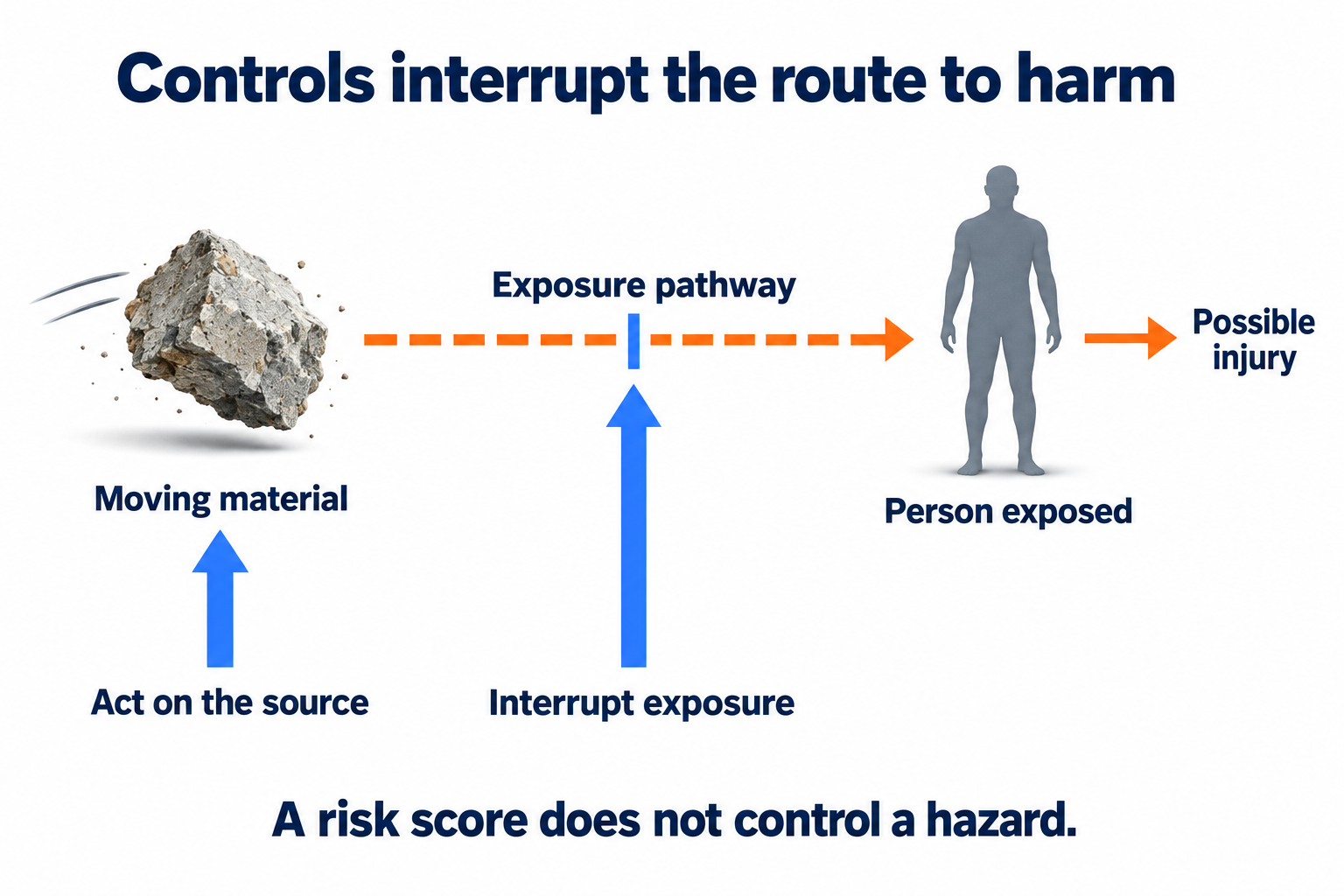
    Hazard, exposure and harmAn orange dashed pathway connects moving concrete material to a person and possible injury. Blue arrows identify intervention at the source and at a break in the exposure pathway. These are causal connections, not travel routes or a barrier design.Open full-size illustration

    A source of potential harm reaches a person or environmental receptor through an exposure pathway. For example, moving material can strike a person who enters its path. The consequence depends on the material, movement and exposure involved.

    Controls act on the source or interrupt the connection before harm occurs. The arrows below the main chain indicate these intervention points. A control must be in place and effective: assigning a risk score does not itself change the hazard or exposure.

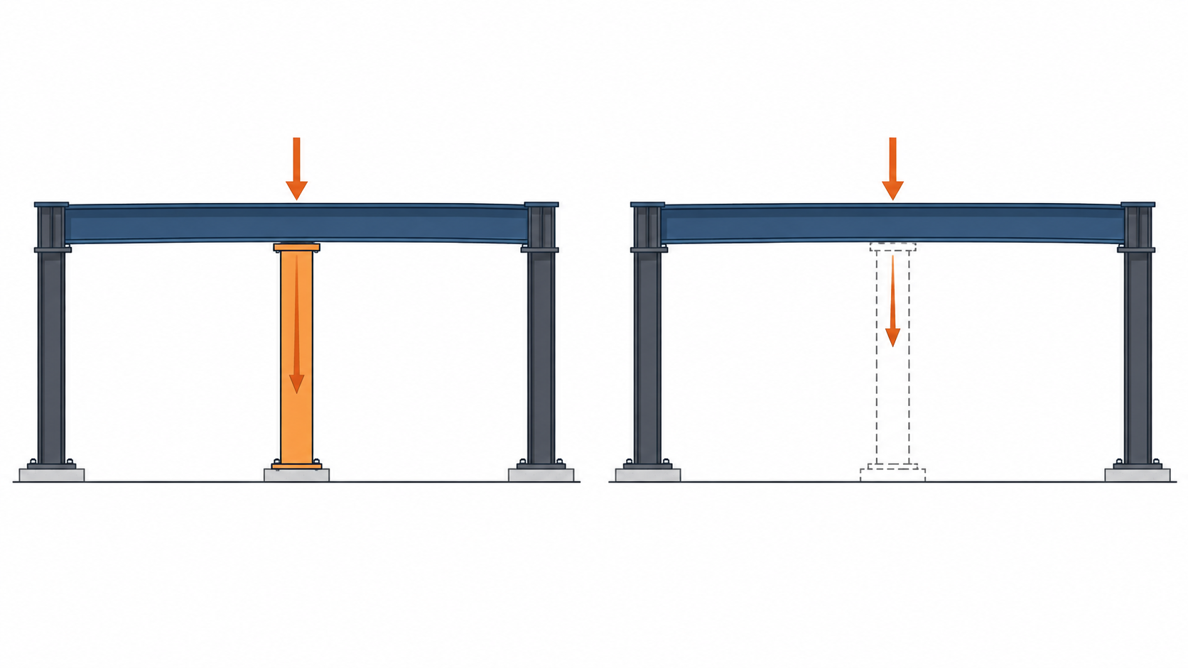
    Case visual LA-11: Left: a beam has end supports and a central support

    LEARNING AID A generic learning aid explains a principle. It does not establish a project fact, hidden condition, capacity, approval or work release.

    Matched beam-and-support bays: a solid central post at left and only its dashed outline at right, with a downward path ending in the gap.Open full-size illustration

    Left: a beam has end supports and a central support. Right: the central support is absent; its dashed outline marks the former position. The interrupted arrow marks the lost direct support path. Redistribution, deformation, remaining capacity and temporary stability are not calculated or shown.

    A generic learning aid explains a principle. It does not establish a project fact, hidden condition, capacity, approval or work release.

    This visual is draft case-study teaching material. Reading it is not an inspection, a measurement or evidence of performance.

    Connections turn separate pieces into a system

    A connection transfers force between components and can also control movement or rotation. Connections may use bolts, welds, reinforcement, anchors, bearings, timber fasteners or other arrangements. Their behaviour depends on details such as material condition, geometry, installation, embedment and the direction of the force. A visible fastener count alone does not establish the connection's capacity.

    Deterioration and alteration can change the original arrangement. Corrosion can reduce material or affect anchors. Decay can weaken timber around a connection. Fire can alter materials and joints. Unrecorded openings or removed braces can interrupt a previously continuous path. Evidence of the original design must therefore be read alongside information about the existing condition.

    For example, a drawing may show the end bearings that carry a roof beam's vertical load. A separate detail shows its lateral restraints at intervals. If only the end bearings are considered, the explanation is incomplete. The beam can have a vertical load route and still require the intermediate restraint to maintain its intended behaviour.

    A structural assessment must connect the applied load, the force-transferring connections, their condition and the changes proposed for the demolition stage. A missing tie or unexplained connection can matter before any obvious failure develops.