
Plans and diagrams
Hazard pathways, document relationships, load paths, drawing views, site interfaces and waste movements can be explained through diagrams, each with defined limits.
Hazard, document and change diagrams
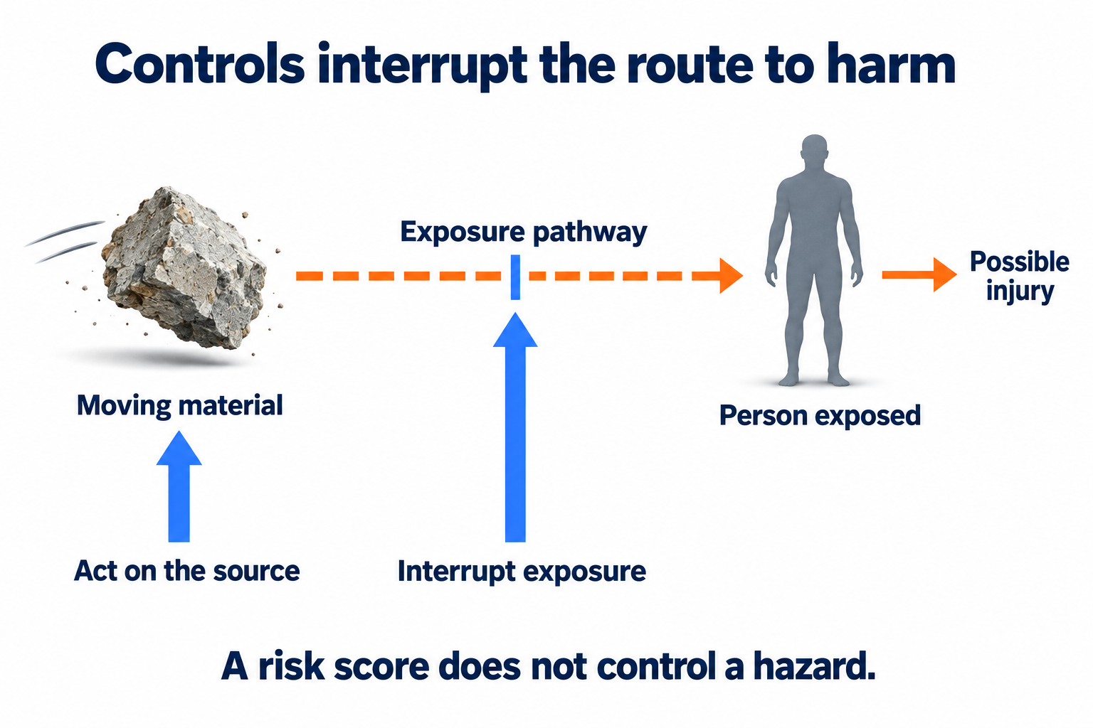
A hazard-pathway diagram connects the source of harm, the route of exposure, the person or environmental receptor and the possible consequence. Controls act on the source or pathway before harm occurs. The diagram explains where prevention acts; it does not calculate a risk score or an exclusion distance.
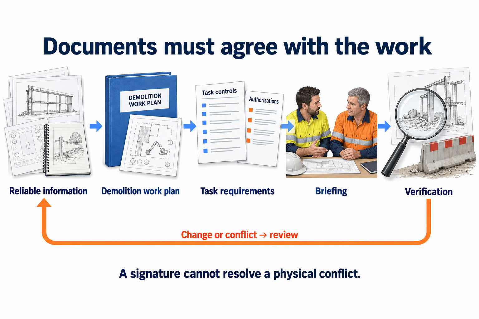
A document relationship diagram connects drawings, observations and specialist findings with project planning, task controls, authorisations, briefing and verification. Changed or conflicting information returns the affected decisions for review. These connections show dependence between decisions, rather than a fixed order in which every document must be produced.
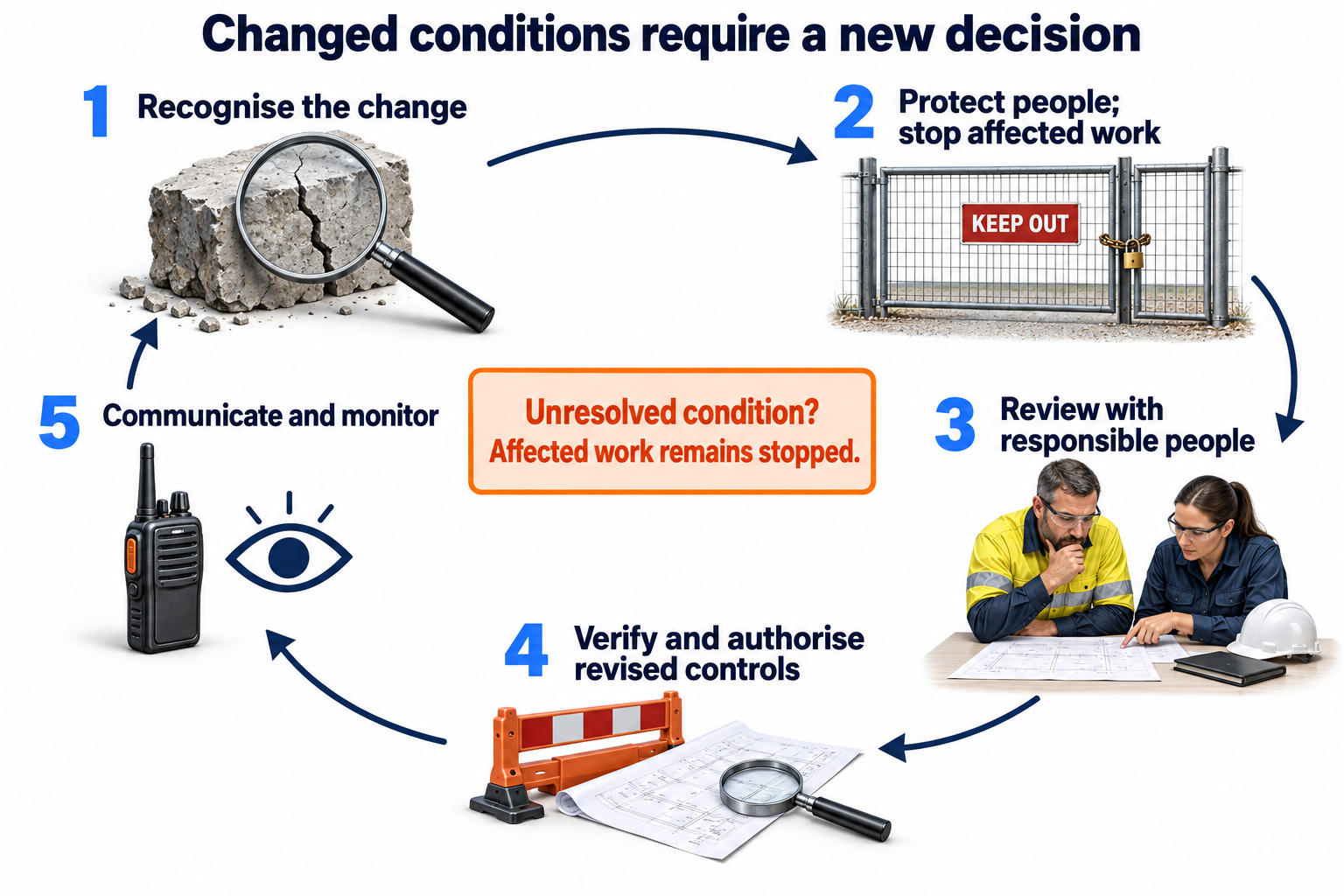
A change diagram connects recognition of a changed condition with protection of people, stopping affected work, referral, review, confirmation of revised controls and communication. Monitoring then tests the new arrangement. An unresolved assumption keeps the affected decision open. The physical shutdown and restart arrangements remain specific to the activity and site.
Hazard, exposure and harm
Controls prevent harm by acting on a hazard or its exposure pathway.
 Open full-size illustration
A source of potential harm reaches a person or environmental receptor through an exposure pathway. For example, moving material can strike a person who enters its path. The consequence depends on the material, movement and exposure involved.
Controls act on the source or interrupt the connection before harm occurs. The arrows below the main chain indicate these intervention points. A control must be in place and effective: assigning a risk score does not itself change the hazard or exposure.
Relationships between project documents
Site information connects planning, task controls, communication and verification.
 Open full-size illustration
Drawings, site observations, engineering information and hazardous-material findings establish the information used for planning. The demolition work plan coordinates the project; task controls and relevant authorisations address the work being undertaken. Briefings communicate the current arrangements, while verification establishes whether those arrangements have been implemented and remain effective.
A change or inconsistency requires the affected information and decisions to be reviewed. Documents must remain consistent with both one another and the physical conditions on site. A repeated signature cannot resolve a conflict between the plan and the work.
Responding to changed conditions
A change requires review of the assumptions and controls governing affected work.
 Open full-size illustration
A changed condition can invalidate the assumptions supporting a work stage. Protecting people and stopping affected work limits further exposure while the responsible people review the change. Revised controls require the appropriate technical input, verification and authorisation before affected work resumes.
The revised arrangement must reach everyone whose work depends on it. Monitoring then establishes whether it remains effective. An unresolved condition is not cleared by the continued existence of an earlier plan. Emergency response follows the site's emergency arrangements and the authority responsible for the incident.
Loads, supports and restraint
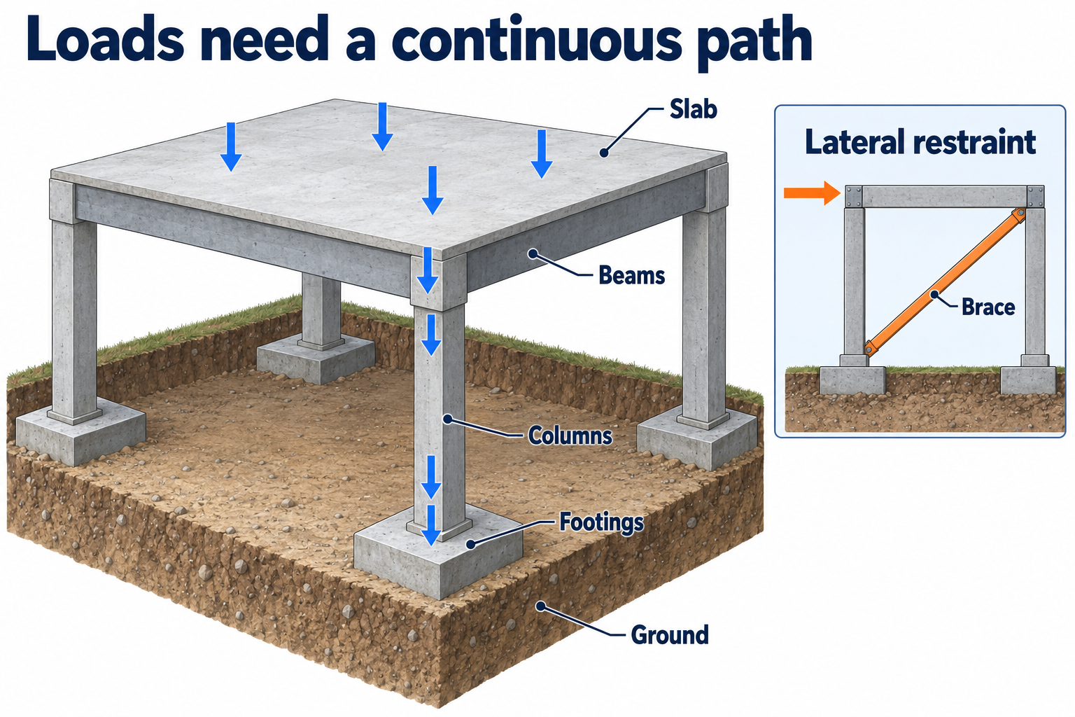
A simple load-path diagram can show actions on a roof or floor passing through beams or supporting members. It can then show their path through columns or loadbearing walls, foundations and the ground. Downward arrows represent the transfer of actions through connected supports. They do not show a demolition sequence.
Lateral actions, bracing, connections and restraint also matter. The vertical chain alone does not explain stability against sideways actions. A structure can depend on elements that restrain movement as well as those carrying gravity loads. Removing or changing a connection can affect the remaining system.
Actual buildings may have direct supports, continuity and concealed dependencies that differ from a simple chain. A conceptual diagram therefore cannot establish member capacity or identify an element that can safely be removed. The structure's current information and the appropriate engineering review are needed to establish how it behaves during the proposed work.
Gravity loads and lateral stability
Structural elements transfer loads through connected supports and restraints.
 Open full-size illustration
Roof and floor loads pass through supporting beams or walls, then through columns or walls, into foundations and the ground. Each connection in the vertical chain represents a dependency: the receiving element must transfer the relevant action to the next support.
Lateral actions involve a different but connected set of relationships. Bracing, connections and restraints limit unwanted movement. An element that carries little gravity load can still provide essential lateral stability. Removing it may change the behaviour of the structure that remains.
Demolition alters loads, connections and restraints as work progresses. The partly dismantled structure must therefore be considered at each stage, using the current engineering information. Hidden construction, deterioration, ground conditions and temporary works may affect the assessment.
The schematic identifies load-transfer relationships, not member capacities or a removal sequence. Stage-specific structural decisions require information about the actual elements, their condition and their connections. An unresolved load path requires technical review.
Plan, elevation and section
A plan is a view from above showing arrangement and boundaries. An elevation shows a face or side, including external form and height relationships. A section represents an imagined cut through a structure, revealing internal and level relationships.
For a simple room, a plan shows where walls and openings lie relative to one another. An elevation shows one face. A section reveals relationships hidden behind that face. The precise view, cut location and direction depend on the drawing's conventions and references.
No single view answers every spatial question. Title blocks, legends, dimensions, notes, specifications and related details establish the context. An illustrative sketch cannot supply a missing project dimension. Where two views disagree, their references and revisions help locate the conflict for authorised clarification.
Plan, elevation and section
Drawing views describe different spatial relationships within the same structure.
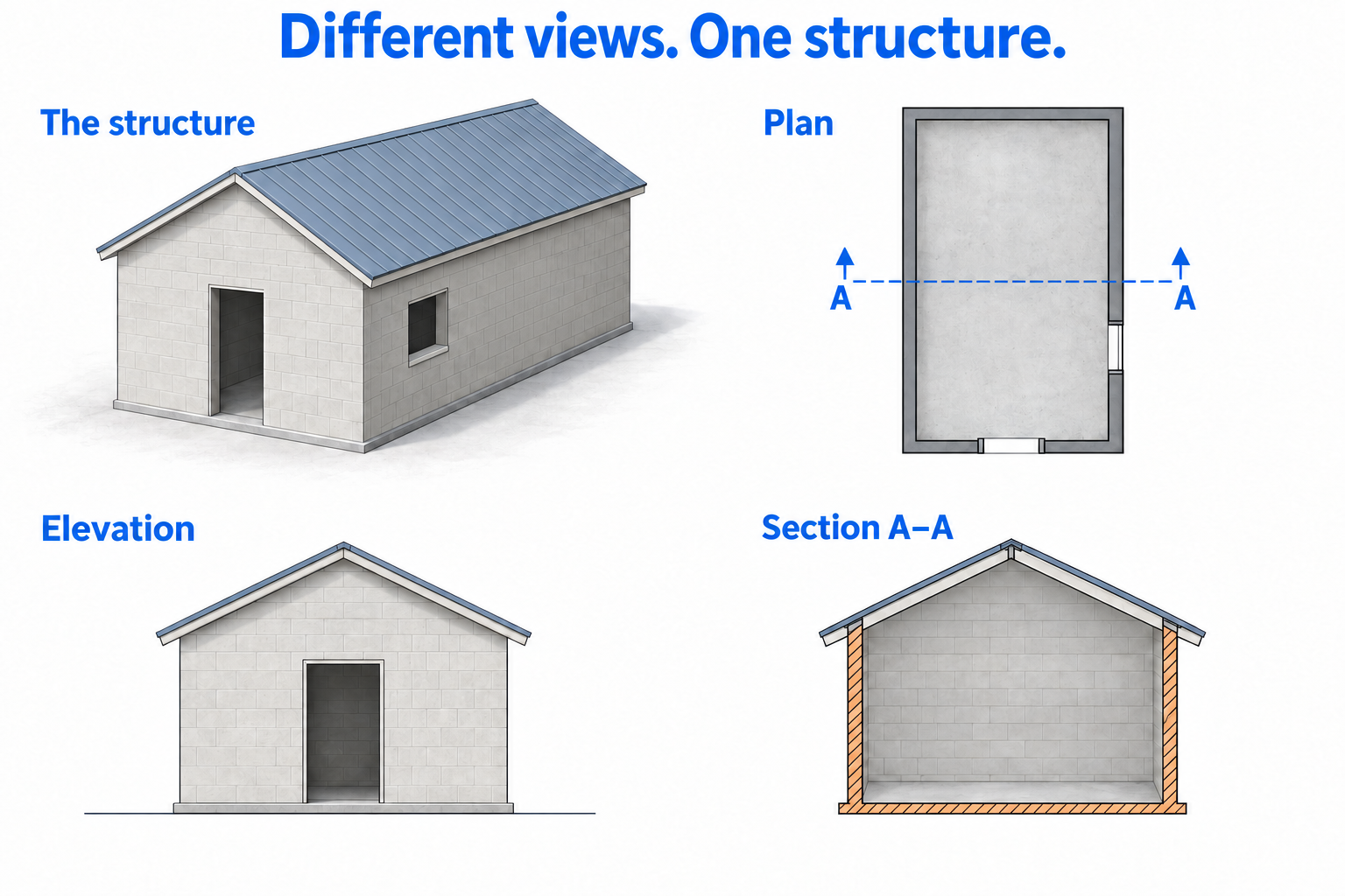 Open full-size illustration
A plan shows the horizontal arrangement viewed from above. An elevation shows the vertical outline of an external face. A section represents a cut through the structure, revealing internal relationships between elements such as roofs, walls and floors.
Drawing references connect these views to orientation, levels, dimensions and details. A plan may locate a connection without establishing its height; an elevation may show its external position without revealing a concealed arrangement. A missing referenced section or detail leaves an information gap.
The illustrated views are not to scale. Apparent line thickness cannot establish structural support, and dimensions cannot be measured from these shapes. On an actual drawing, interpretation depends on the project identity, revision, issue purpose, legend, units and applicable notes.
Plant, people and surrounding activities
An interface diagram can connect plant and loads, workers and visitors, and neighbours and the public with the controls that protect them. The shared controls include physical separation, access arrangements, agreed communication, monitoring and review of change.
Lines between these groups describe relationships; they are not travel routes. A conceptual interface diagram does not establish a traffic layout, turning circle or exclusion distance. Effective separation depends on the physical arrangement and its supporting controls, not solely on a painted line, sign or spotter.
A delivery can affect visitors, a changed storage area can affect workers, and dust or debris can reach people beyond the fence. These relationships can change while the central task remains the same. The actual hazards, plant, people and surrounding conditions determine the controls needed in the project plan.
Plant, people and public interfaces
Separation depends on coordinated physical controls, access arrangements and communication.
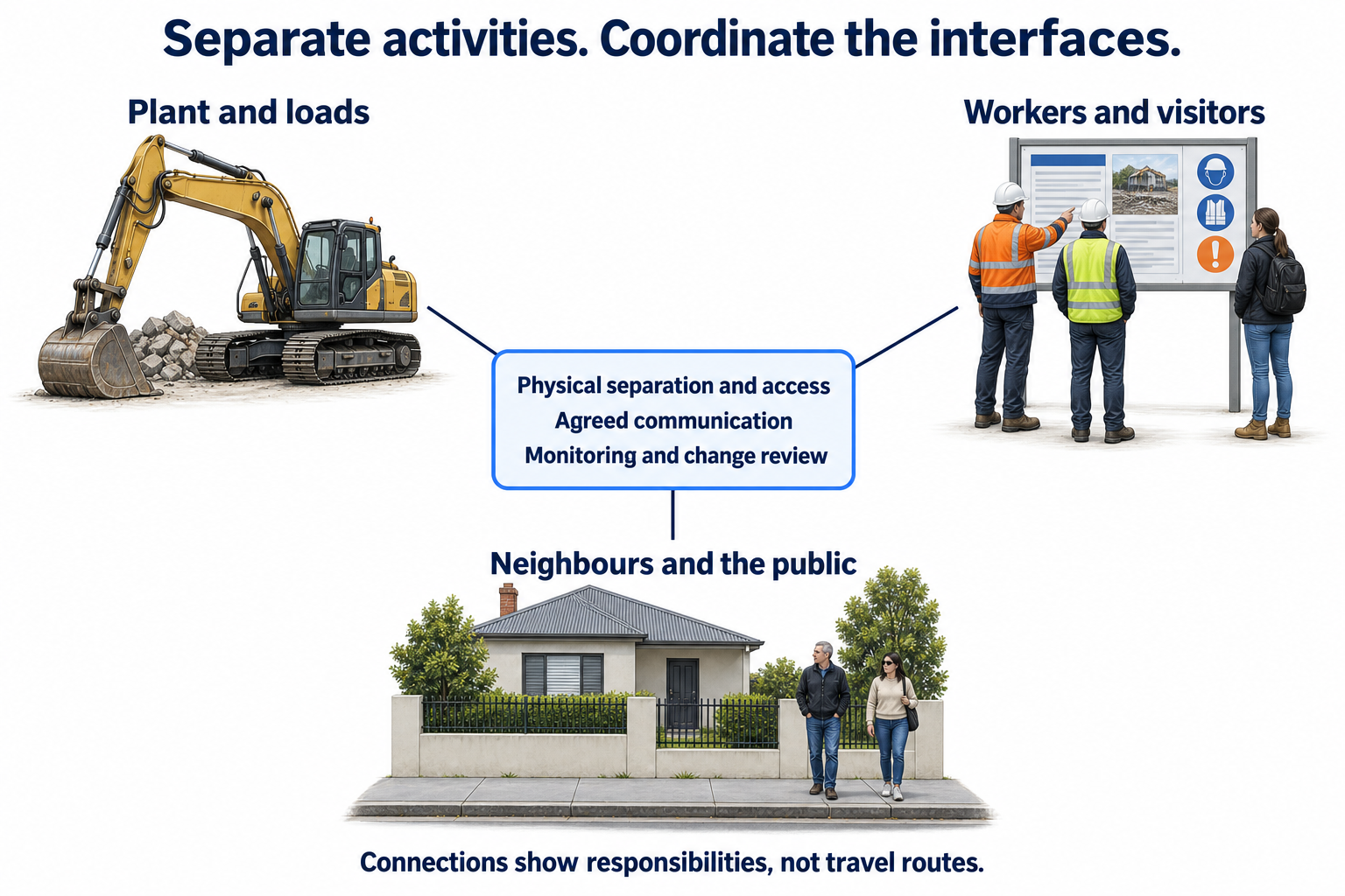 Open full-size illustration
Plant and loads, workers and visitors, and neighbouring properties and the public create interacting demands on a demolition site. The three groups in the diagram connect to shared controls: physical separation, access rules, communication, monitoring and review of changes. The lines represent these relationships, not movement routes.
The arrangement must also preserve emergency and authorised access. Its design depends on the work, plant, material behaviour, surrounding uses and relevant technical information. A boundary on a drawing does not itself provide a barrier, contain flying debris, verify ground capacity or protect an adjoining structure.
Deliveries, loading operations, changed pedestrian routes and open gates can create new connections between previously separated activities. Responsibility for access and communication must be clear. A sign or a spotter alone cannot establish that every exposure has been controlled.
Material identity and the receiving destination
A waste-pathway diagram links characterisation, segregation, lawful transport, destination checks and the records needed to reconcile movements. Material identity must remain traceable through the whole movement.
The position of a box on a diagram can be misleading if it is read as a work sequence. Destination suitability needs to be confirmed before dispatch, even when the destination appears after transport in the picture. The receiver must be able to accept the particular waste under the applicable conditions. A general business name or a driver's assurance does not establish this.
Receipts need to be linked to the material and movement they concern. Differences in descriptions or quantities require explanation, with estimates distinguished from measured values. A transaction docket does not establish every legal condition, and a simple pathway diagram does not supply classification thresholds, sampling requirements or resource-recovery exemptions.
Waste identification and traceability
Records connect the material, transport arrangements and authorised receiving destination.
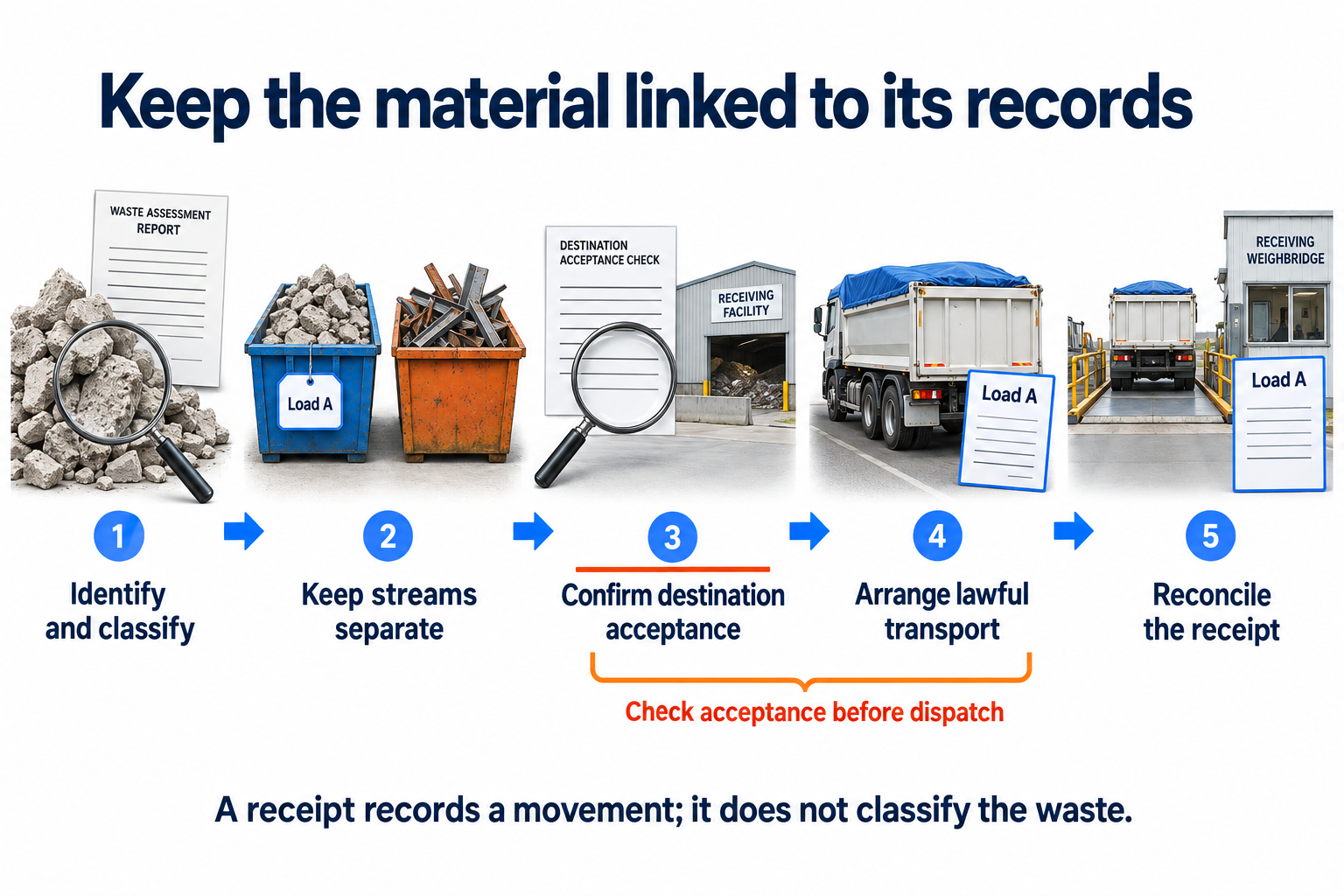 Open full-size illustration
Waste management begins with material identification and the required characterisation or classification. Appropriate segregation preserves the identity of each stream. The load must then be connected to lawful transport arrangements and a receiving facility authorised to accept that waste. Destination suitability must be confirmed before dispatch.
Records preserve the connection between what left the site, where it went and what was received. A receipt from a facility does not establish the destination of every other load or confirm that the recorded description matches the material. An estimated quantity must remain distinguishable from a measured weighbridge result.
Classification, testing, transport and resource recovery requirements depend on the material and circumstances. If material identity or destination acceptance is unresolved, changing a label does not resolve the underlying uncertainty. The affected movement needs the appropriate review before it proceeds.
Traceability continues through segregation, stockpiling, load-out and close-out. Records must describe the physical movement accurately, including discrepancies that require reconciliation.
Reading a diagram with its supporting record
A diagram shows selected relationships. Its supporting description and records explain what those relationships mean and the information on which they depend. In a material-transfer control record, identity and scope establish the material and activity; the hazard description explains exposure; control ownership identifies responsibility; and verification records what was checked.
Terms also affect interpretation. A check, a review and an authorisation do not mean the same thing. A drawing revision identifies a version, while its issue purpose describes the use for which it was issued. Clear definitions preserve these distinctions when information passes between people.
Simplification is useful for explaining a relationship, but it leaves out detail. A diagram cannot replace the applicable technical standard, site drawing or approval. Its stated scope and the current controlling information determine what can be inferred from it.
Interpreting a control record
A control record for a material-transfer area needs to identify the activity, location, revision and intended use. These details establish whether the document applies to the work. Its supporting information and unresolved assumptions are equally important: changing a heading does not make an unrelated record applicable.
A hazard entry must explain the route to harm. Terms such as plant or debris identify a subject but not the exposure. The record needs to establish how movement or material could reach workers, visitors, neighbouring property or an environmental receptor. Deliveries and changing work areas can alter those pathways.
The control entry distinguishes measures that are proposed from those already implemented. It identifies how each measure reduces exposure, who establishes and maintains it, and what technical information it depends on. Exclusion distances and load limits require the relevant site-specific basis; they cannot be derived from a generic form.
Verification must address the condition being relied upon. A photograph may establish the location of a sign, but it cannot establish the capacity of a structural support. A signature may record acknowledgement without verifying the assumptions behind the arrangement.
If a delivery blocks the planned route, the review must address the changed movement and exposure. The revised arrangement must be communicated and obsolete instructions withdrawn from use. Traffic arrangements, the demolition work plan, relevant safe work method statements, emergency access and briefings must remain consistent. A permit authorises a defined activity under specified conditions; it does not replace unrelated technical confirmations.
Technical terms
Hazard — A source or situation with potential to cause harm.
Risk — The possibility of harm, considered with its likelihood and consequence in context.
Exposure — The opportunity for a person or receptor to come into contact with a hazard.
Consequence — The harm or loss that could result.
Control — A measure that eliminates or reduces risk.
Remaining risk — Risk considered after the specified controls have actually been applied.
Elimination — Removing the hazard or hazardous exposure from the work.
Substitution — Replacing a hazard with a less hazardous alternative.
Isolation — Separating people from a hazard.
Engineering control — A physical or designed measure that acts on a hazard or exposure pathway.
Administrative control — An arrangement such as procedures, scheduling, information or supervision.
PPE — Personal protective equipment.
RPE — Respiratory protective equipment.
SWMS — Safe work method statement; a document for relevant high-risk construction work.
DWP — Demolition work plan.
Permit — A bounded authorisation within a defined control system, not universal proof of safety.
Induction — Introduction to relevant site conditions, responsibilities and arrangements.
Pre-start — A check or briefing before work or equipment use; distinct from scheduled servicing.
Verification — Checking evidence that the required condition or control exists and works as intended.
Consultation — Sharing relevant information, hearing affected workers' views and considering them in decisions.
Load path — The connected route by which forces pass through a structure to its supports.
Compression — A pushing action within a material or member.
Tension — A pulling action within a material or member.
Bending — A response to loading that tends to curve a member.
Shear — Action tending to make parts move past one another.
Temporary works — Engineered or other temporary arrangements supporting construction or demolition needs; specialist design and control may be required.
Respirable dust — Particles small enough to reach deep into the lungs.
LEL — Lower explosive limit; the lowest flammable gas or vapour concentration in air at which flame can propagate under the relevant conditions. Percentage of LEL is not percentage gas concentration or a safe-breathing decision.
Receptor — The person, property or environmental feature potentially affected.
Change control — The process of recognising a change, reviewing affected assumptions and controls, and communicating the revised arrangement.
Air monitoring — Competently planned measurement of airborne contaminants to assess exposure and control effectiveness.
Health monitoring — Medical monitoring for health effects, carried out or supervised by an appropriately experienced doctor when required.