Skip to reading
    Book overview
    THE DEMOLITION SUPERVISOR’S FIELDBOOK / CHAPTER 43
    Part VI · Plans, structures and engineering interface

    Structural behaviour: compression, tension, bending and combined actions

    Stress, strain, bending, shear and torsion describe different aspects of structural response. Material behaviour, connections and restraint determine whether a member can resist the actions placed on it.

    Force, stress and strain describe different things

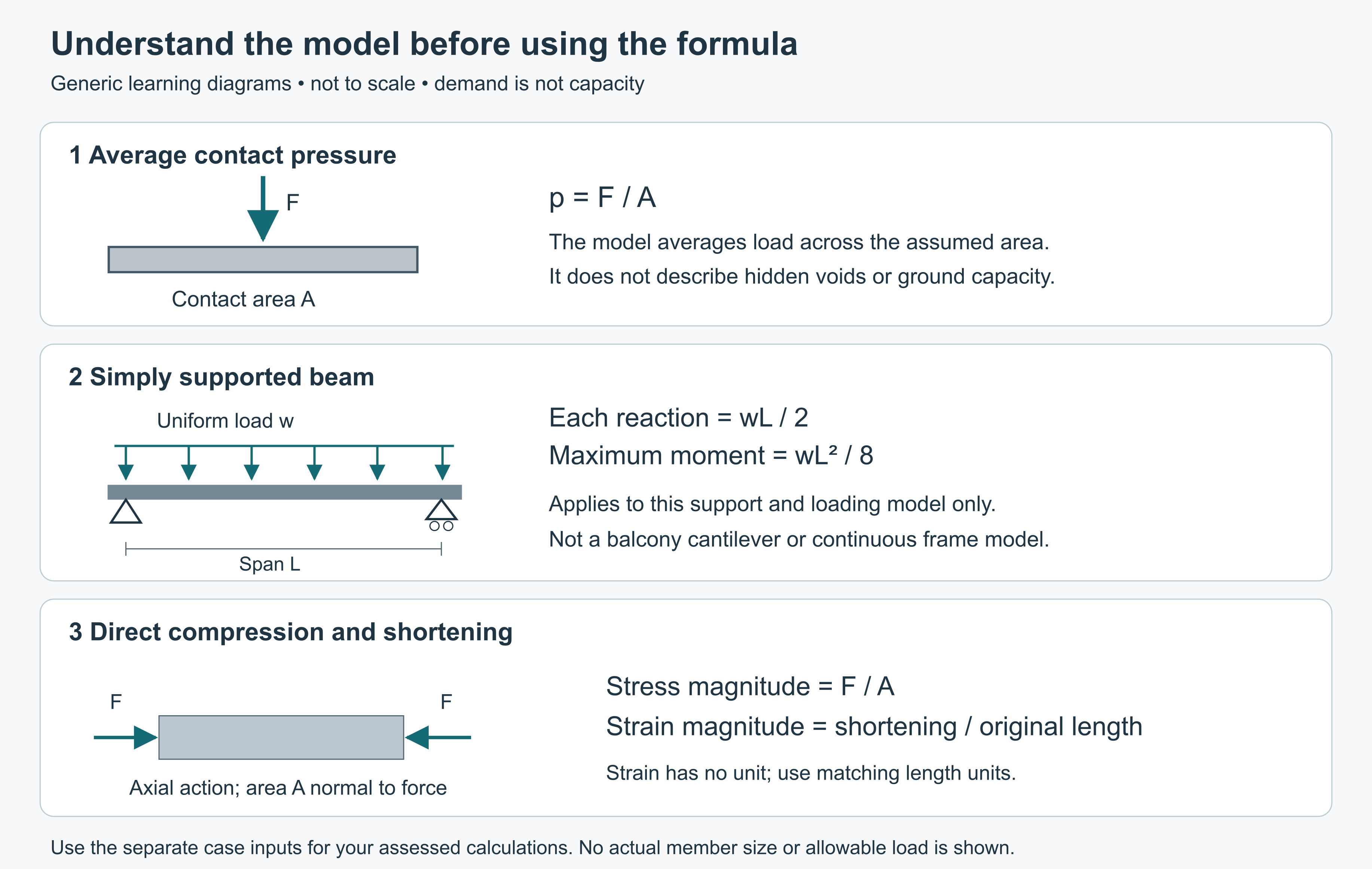
    Force is a push or pull and has direction. Structural force is commonly expressed in newtons or kilonewtons; one kilonewton is one thousand newtons. Stress describes force distributed over an area. Strain describes deformation relative to an original dimension. Neither stress nor strain is simply another word for load.

    In an ideal axial calculation, a force of twelve kilonewtons acts uniformly through a cross-sectional area of six hundred square millimetres. Twelve kilonewtons is twelve thousand newtons. Dividing twelve thousand by six hundred gives twenty newtons per square millimetre, equivalent to twenty megapascals. In the same ideal calculation, suppose the effective area is halved to three hundred square millimetres while force stays the same. The average stress then doubles to forty megapascals.

    At unchanged force, loss of effective section increases average stress. Average stress alone does not establish the capacity of a corroded member. Real stress can be uneven because of holes, notches, eccentricity, bending and connections, and capacity depends on the material, stability and design criteria.

    For a strain calculation, a two-thousand-millimetre specimen lengthens by zero point six millimetres. Dividing zero point six by two thousand gives zero point zero zero zero three, or zero point zero three percent. Strain has no length unit because the two lengths are divided. The calculation says how much relative change occurred; it does not say whether that change is acceptable or whether the material will recover after unloading.

    Technical terms

    Hazard — A source or situation with potential to cause harm.

    Risk — The possibility of harm, considered with its likelihood and consequence in context.

    Exposure — The opportunity for a person or receptor to come into contact with a hazard.

    Consequence — The harm or loss that could result.

    Control — A measure that eliminates or reduces risk.

    Remaining risk — Risk considered after the specified controls have actually been applied.

    Elimination — Removing the hazard or hazardous exposure from the work.

    Substitution — Replacing a hazard with a less hazardous alternative.

    Isolation — Separating people from a hazard.

    Engineering control — A physical or designed measure that acts on a hazard or exposure pathway.

    Administrative control — An arrangement such as procedures, scheduling, information or supervision.

    PPE — Personal protective equipment.

    RPE — Respiratory protective equipment.

    SWMS — Safe work method statement; a document for relevant high-risk construction work.

    DWP — Demolition work plan.

    Permit — A bounded authorisation within a defined control system, not universal proof of safety.

    Induction — Introduction to relevant site conditions, responsibilities and arrangements.

    Pre-start — A check or briefing before work or equipment use; distinct from scheduled servicing.

    Verification — Checking evidence that the required condition or control exists and works as intended.

    Consultation — Sharing relevant information, hearing affected workers' views and considering them in decisions.

    Load path — The connected route by which forces pass through a structure to its supports.

    Compression — A pushing action within a material or member.

    Tension — A pulling action within a material or member.

    Bending — A response to loading that tends to curve a member.

    Shear — Action tending to make parts move past one another.

    Temporary works — Engineered or other temporary arrangements supporting construction or demolition needs; specialist design and control may be required.

    Respirable dust — Particles small enough to reach deep into the lungs.

    LEL — Lower explosive limit; the lowest flammable gas or vapour concentration in air at which flame can propagate under the relevant conditions. Percentage of LEL is not percentage gas concentration or a safe-breathing decision.

    Receptor — The person, property or environmental feature potentially affected.

    Change control — The process of recognising a change, reviewing affected assumptions and controls, and communicating the revised arrangement.

    Air monitoring — Competently planned measurement of airborne contaminants to assess exposure and control effectiveness.

    Health monitoring — Medical monitoring for health effects, carried out or supervised by an appropriately experienced doctor when required.

    Compression and tension interact with material behaviour

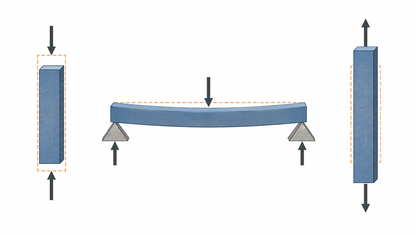
    Compression tends to shorten a member along the direction of the force. Tension tends to lengthen it. A member carrying an axial force is an idealisation in which the force acts along its axis. If the force acts away from that axis, it can also create bending. Real connections and geometry determine whether an apparently simple load is actually eccentric.

    Materials respond differently. Concrete is comparatively effective in compression but has limited tensile resistance, so reinforced-concrete design uses reinforcement to carry specified tensile actions. Steel can carry tension and compression. But a slender steel component may become unstable in compression before its material reaches the strength someone expects from a sample. Timber properties depend on direction relative to the grain, moisture, defects and condition. Masonry's behaviour depends on units, mortar, geometry, connections and restraint.

    Elastic deformation is recoverable when the load is removed within the relevant range. Plastic deformation is permanent. Ductility describes an ability to undergo significant deformation before failure; brittle behaviour involves relatively little such deformation. These concepts do not promise a visible warning. A connection can fail differently from the main material, and deterioration can change the behaviour of the assembly.

    An important confusion is to treat stiffness and strength as identical. Stiffness describes resistance to deformation; strength concerns resistance to failure under the relevant action. A member can be relatively stiff yet fail in a brittle manner, or be strong but deflect beyond an acceptable condition. Structural assessment considers both, together with stability and the requirements of the whole system.

    Bending combines force and distance

    Bending occurs when actions tend to curve a member. In the ideal elastic model, consider a simple beam under downward loading. One region can be in compression while another is in tension, with a neutral region between them. The orientation of those regions depends on the support and loading arrangement. It is not always correct to assume the same face is in tension everywhere.

    A bending moment expresses a turning effect and is measured in force multiplied by distance, such as kilonewton-metres. It is not a mass. For example, a straight beam is supported at each end, six metres apart, and carries one downward point load of six kilonewtons at the middle. Assume ideal simple supports, static loading and no self-weight or other actions. By symmetry and vertical balance, each support reaction is three kilonewtons.

    At midspan, the three-kilonewton reaction acts over three metres on either half of this ideal beam. The bending moment there is nine kilonewton-metres. This is the calculated bending action, not the beam's resistance. Establishing capacity also requires the member's section, material, connections and stability conditions.

    Moving a load, changing a support or changing the span changes the action pattern. A continuous beam over several supports behaves differently from the simple model. A cantilever has another arrangement, with its support needing to resist the relevant turning effect. Changing continuity or restraint during demolition can therefore change bending behaviour without an obvious change in the remaining beam's appearance.

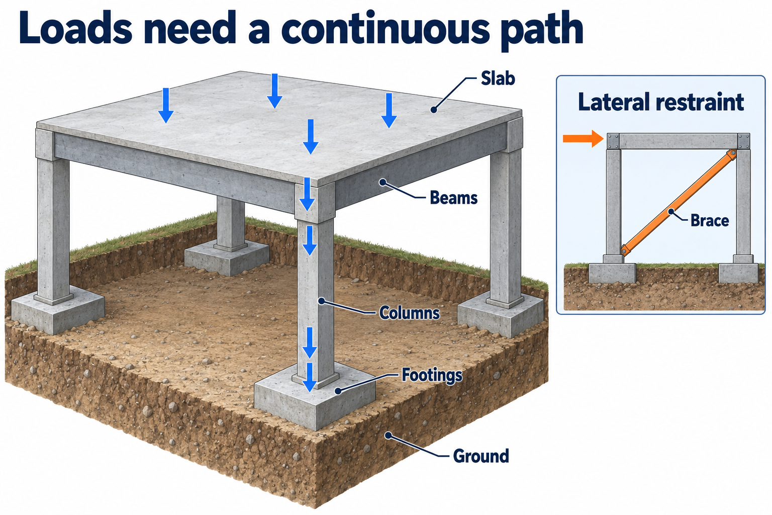
    Gravity loads and lateral stabilityGravity loads pass from roofs and floors through beams or walls, columns or walls, foundations and ground. A separate lateral relationship highlights bracing, connections and restraint. This schematic gives no capacities or removal sequence.

    Roof and floor loads pass through supporting beams or walls, then through columns or walls, into foundations and the ground. Each connection in the vertical chain represents a dependency: the receiving element must transfer the relevant action to the next support.

    Lateral actions involve a different but connected set of relationships. Bracing, connections and restraints limit unwanted movement. An element that carries little gravity load can still provide essential lateral stability. Removing it may change the behaviour of the structure that remains.

    Demolition alters loads, connections and restraints as work progresses. The partly dismantled structure must therefore be considered at each stage, using the current engineering information. Hidden construction, deterioration, ground conditions and temporary works may affect the assessment.

    The schematic identifies load-transfer relationships, not member capacities or a removal sequence. Stage-specific structural decisions require information about the actual elements, their condition and their connections. An unresolved load path requires technical review.

    Shear and torsion describe other action patterns

    Shear tends to make adjacent parts of a material slide relative to one another. In a beam, shear is connected to the transfer of transverse loads towards supports. Connections can also carry shear through bolts, welds, fasteners or other details. Shear failure is not simply a member bending too far, and the relevant resistance may be concentrated in a small connection region.

    Punching shear is a local action around a concentrated support or load in a slab. It helps explain why a broad floor area and a small contact area raise different questions. A slab can require consideration of local failure as well as overall bending. Its appearance from above does not establish its resistance to either.

    Torsion is twisting about a member's axis. An off-centre force can create a twisting effect as well as other actions. A connection or cross-section that resists one direction effectively may behave differently in torsion. The load's location relative to the member is therefore part of the structural question, not a minor geometric detail.

    Combined actions are normal in real structures. A column can carry compression with bending. A beam can experience bending, shear and torsion together. Wind, gravity, applied plant forces and temporary restraints can interact. It is unsafe to check each action informally against a remembered isolated value and assume the combined condition is acceptable. The structural design process considers their interaction, relevant combinations and failure modes.

    Buckling is a stability problem

    Buckling is a loss of stability in which a member or part of a member deforms into another shape under load. A slender compression member can move sideways; a thin plate element can buckle locally; a beam can experience a coupled sideways and twisting instability. These are related ideas, not one universal failure mechanism.

    Unsupported length, cross-sectional shape, end restraint, intermediate restraint, material stiffness and imperfections all influence behaviour. A member that is restrained at intervals can behave very differently after those restraints are lost. A connection assumed to prevent rotation or translation must actually provide that function. The structural system, not just the member catalogue, determines the relevant condition.

    Two otherwise similar slender compression members can have different unsupported lengths. The longer unrestrained condition is generally more vulnerable to instability, all else being equal. Capacity for a particular member requires the actual geometry, restraints, loads, imperfections and design rules.

    A common confusion is to equate the absence of crushing with adequate compression capacity. Buckling can occur while the material has not reached a simple crushing or yielding limit. Another is to assume that a member which carried yesterday's loads will carry today's loads after adjoining construction is removed. The restraint conditions may have changed. Recognising this mechanism explains why seemingly secondary ties and bracing must remain within the stage-specific structural plan.

    Structural distress and the limits of observation

    Structural distress can appear as unexpected movement, cracking, distortion, separation at connections, falling fragments or a change in alignment. These observations can be important, but their cause and significance depend on the material, system, history and current work. A crack pattern is not a universal diagnosis, and the absence of visible distress does not demonstrate adequate capacity.

    A report that a member has moved sideways records an observation. A statement that it has buckled interprets the mechanism and may require technical confirmation. A connection has visibly separated is different from guessing its original capacity. Useful communication records the location, time, relevant activity and observed change without exposing anyone to obtain a closer view.

    Where movement, damaged supports or a changed structural assumption creates uncertainty, maintain the applicable stop and exclusion arrangements and seek the required competent structural response. Do not test the structure by adding a load, removing another piece or approaching it to see whether it moves again.

    The structural assessment needs to establish the forces and where they act, the material and connections resisting them, and the restraints preventing instability. A changed assumption in any of these can affect the conditions for the demolition stage.

    Responding to changed conditionsChanged conditions lead to protection of people and a stop to affected work, review by responsible people, verification of revised controls, communication and continued monitoring. Unresolved conditions prevent affected work from resuming.

    A changed condition can invalidate the assumptions supporting a work stage. Protecting people and stopping affected work limits further exposure while the responsible people review the change. Revised controls require the appropriate technical input, verification and authorisation before affected work resumes.

    The revised arrangement must reach everyone whose work depends on it. Monitoring then establishes whether it remains effective. An unresolved condition is not cleared by the continued existence of an earlier plan. Emergency response follows the site's emergency arrangements and the authority responsible for the incident.