
Floors, walls, roofs, cladding, columns and retaining systems
Floors, walls, roofs and cladding carry loads and often restrain other elements. Their concealed connections, material condition and relationship to soil and water affect behaviour during demolition.
A floor surface does not reveal its supporting system
A slab on ground transfers its relevant loads into the supporting ground through its construction. A suspended floor spans between supports over a space. Timber joists, steel beams, reinforced-concrete systems and precast units can all form suspended floors. A surface finish may hide the system beneath it, so appearance from above cannot establish how the floor carries load.
Some slabs principally span in one direction; others distribute bending in two directions. A flat slab can transfer load directly to columns, while another floor uses beams between slab and columns. Local behaviour near openings, concentrated loads and supports matters alongside overall span behaviour. Punching around a column region is one example of a local issue that a general floor-area description does not address.
Prestressed concrete uses deliberately introduced internal forces. Pre-tensioned and post-tensioned systems achieve that condition through different construction arrangements. Tendons, anchorage zones and their continuity can be critical, and altering them can release stored energy or change the supporting system. A visible concrete strip cannot be assumed to be ordinary reinforced concrete. Tendon location, cutting or release requires the specific engineering and work arrangements.
A ground-supported appearance is also not proof against hidden voids, tanks, service trenches or earlier excavations. A floor assessment for demolition needs the actual system, condition and proposed temporary loads. Suitability for a machine, a stockpile or impact cannot be established from the original occupancy or an old load sign. Nor can it be established from the fact that people have walked there. The relevant question is how this particular load will be carried through this particular floor in the proposed stage.
Gravity loads and lateral stability
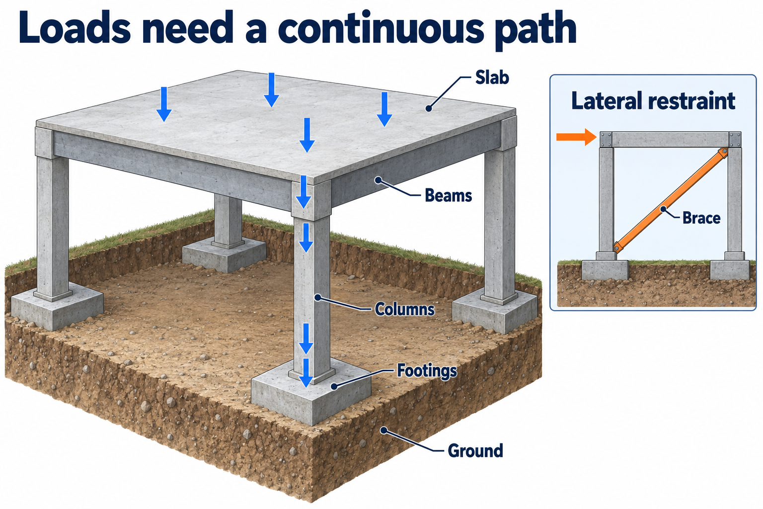
Structural elements transfer loads through connected supports and restraints.
 Open full-size illustration
Roof and floor loads pass through supporting beams or walls, then through columns or walls, into foundations and the ground. Each connection in the vertical chain represents a dependency: the receiving element must transfer the relevant action to the next support.
Lateral actions involve a different but connected set of relationships. Bracing, connections and restraints limit unwanted movement. An element that carries little gravity load can still provide essential lateral stability. Removing it may change the behaviour of the structure that remains.
Demolition alters loads, connections and restraints as work progresses. The partly dismantled structure must therefore be considered at each stage, using the current engineering information. Hidden construction, deterioration, ground conditions and temporary works may affect the assessment.
The schematic identifies load-transfer relationships, not member capacities or a removal sequence. Stage-specific structural decisions require information about the actual elements, their condition and their connections. An unresolved load path requires technical review.
Walls can support, restrain, separate and retain
A wall can have several functions at once. It may carry gravity loads, resist lateral forces, restrain connected members, retain soil, provide fire separation or form an environmental enclosure. Describing a wall as non-load-bearing usually addresses a particular structural role. It does not prove that removing it has no consequence for stability or the surrounding work.
Masonry walls consist of units and joints acting as an assembly. Their response depends on geometry, material condition, bonding, reinforcement where present, supports and restraint. A wall may be relatively effective under one action and vulnerable out of its plane. Loss of support from a roof, floor or return wall can change the condition substantially. Height or thickness viewed in isolation is not a stability assessment.
Framed partitions, infill panels and shear walls can look similar after finishes conceal their construction. An infill panel may interact with its surrounding frame even where it was not intended as the principal lateral system. A shear wall is deliberately part of a lateral-force path. Openings and later alterations can change both intended and actual behaviour.
Shared and boundary walls add questions about ownership, retained buildings, weatherproofing and adjacent support. The technical significance of a connection must be resolved independently of the project's preferred scope line. For example, removing an enclosure beside a retained wall can remove shelter or restraint that the wall previously received. Each relevant role needs to remain accounted for in the work plan and structural information.
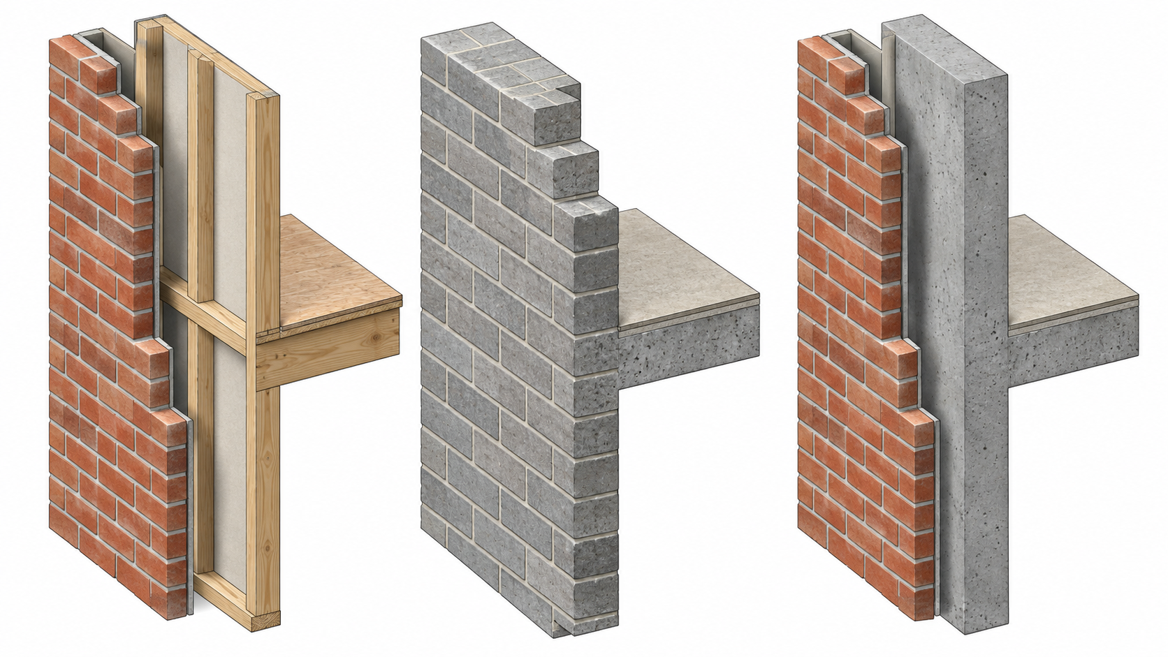
Banksia provides a useful comparison between brick appearance and structural role. Its initial fictional records specify veneer over timber framing. LA-10 contrasts that family with supporting masonry and brick facing in front of a separate structural wall. The outside face can look similar while the support relationship differs.
Use the declared case model when discussing that exercise. For an actual building, verify the wall's construction, connections and role rather than choosing the family that resembles its photograph. This matters when a wall is proposed for removal: the appearance alone does not tell you what support or restraint would change.
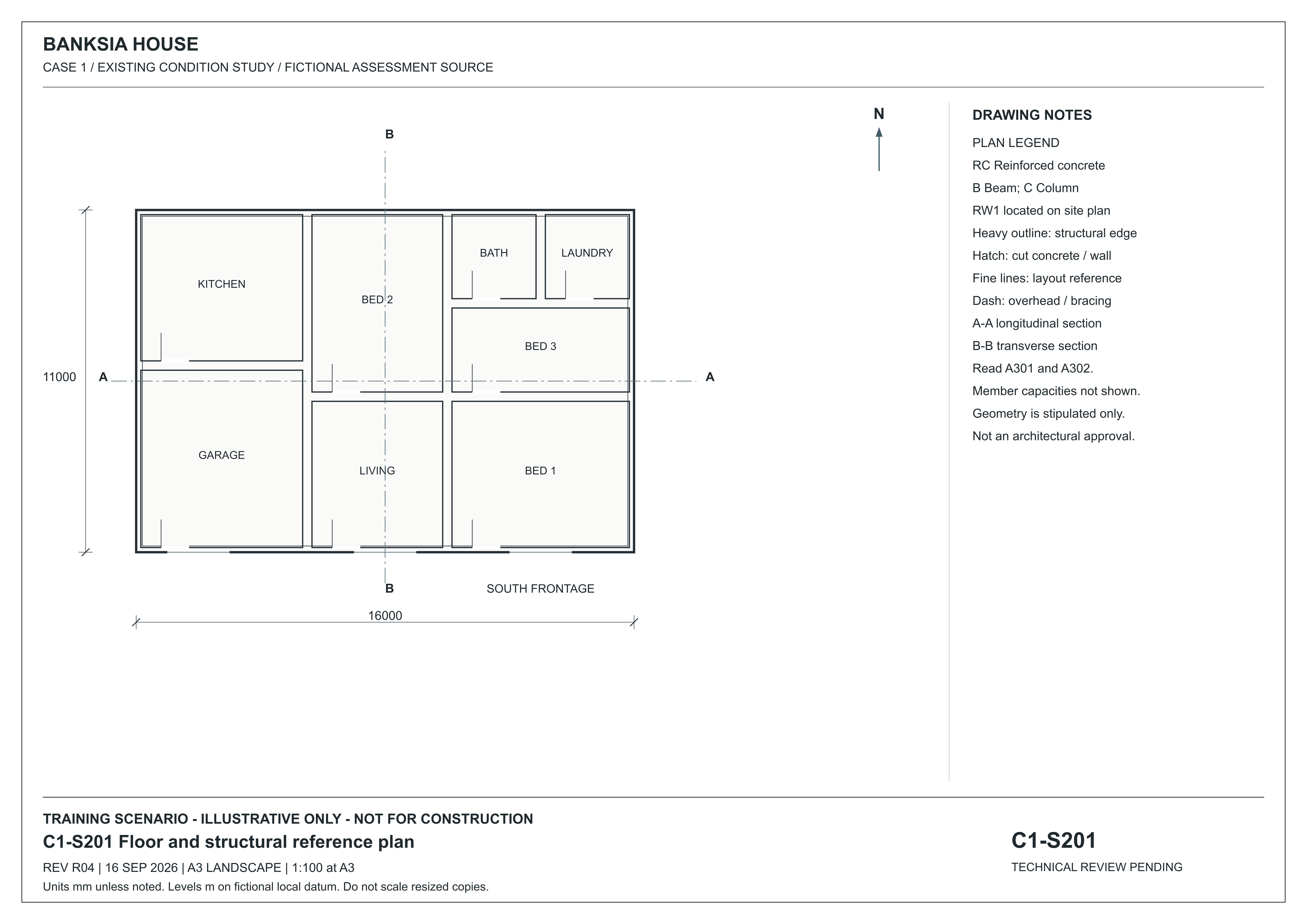
Floor and structural reference plan
CONTROLLED FICTIONAL TRAINING RESOURCE Use the record and its stated limitation. Do not infer hidden support, services or approvals from the image alone.
 Open full-size illustration
C1-S201 R04 – Floor and structural reference plan. Structural and floor reference plan with controlled dimensions, section references and stipulated framing. Room layouts are context; no structural capacities are implied. Reproduced in this guide at reduced size; use written dimensions, not a ruler on this page.
Use the record and its stated limitation. Do not infer hidden support, services or approvals from the image alone.
This visual is draft case-study teaching material. Reading it is not an inspection, a measurement or evidence of performance.
Facing brick and load-bearing masonry
LEARNING AID A generic learning aid explains a principle. It does not establish a project fact, hidden condition, capacity, approval or work release.
 Open full-size illustration
Left: brick facing with timber framing behind. Centre: solid masonry supporting a floor edge. Right: brick facing in front of a separate structural wall. The layer and support relationships differ even when exterior brick is visible. These are simplified families, not construction details or evidence about a case-study wall.
A generic learning aid explains a principle. It does not establish a project fact, hidden condition, capacity, approval or work release.
This visual is draft case-study teaching material. Reading it is not an inspection, a measurement or evidence of performance.
Members and their joints form a connected skeleton
Beams commonly transfer transverse loads towards supports, while columns commonly carry forces along a vertical member. These are useful descriptions, not exclusive action categories. Beams can also carry axial force and torsion; columns can carry bending and shear as well as compression. A member's actual role depends on the complete arrangement.
Joints govern how forces and movements pass between members. A bearing detail may permit rotation while carrying a vertical reaction. A moment connection is intended to transfer a turning effect as part of its design. Bracing connections transmit forces that restrain lateral movement. None of these functions can be confirmed merely because two components touch or a weld is visible.
Column bases connect the above-ground system to foundations. Base plates, anchors, grout, concrete and the footing each have a role in the relevant force path. Damage or alteration at a small connection region can affect a much larger area of supported construction. Covers and finishes may conceal important condition information.
Transfer beams and other transfer members deserve particular attention because they redirect loads between levels or grids. A column above may not align with a column below. Removing construction beneath what appears to be an open floor can therefore affect loads originating elsewhere. In reading a structural package, follow each relevant member to its actual supports and connection details. Size, material name and previous performance alone cannot establish adequacy after those dependencies change.
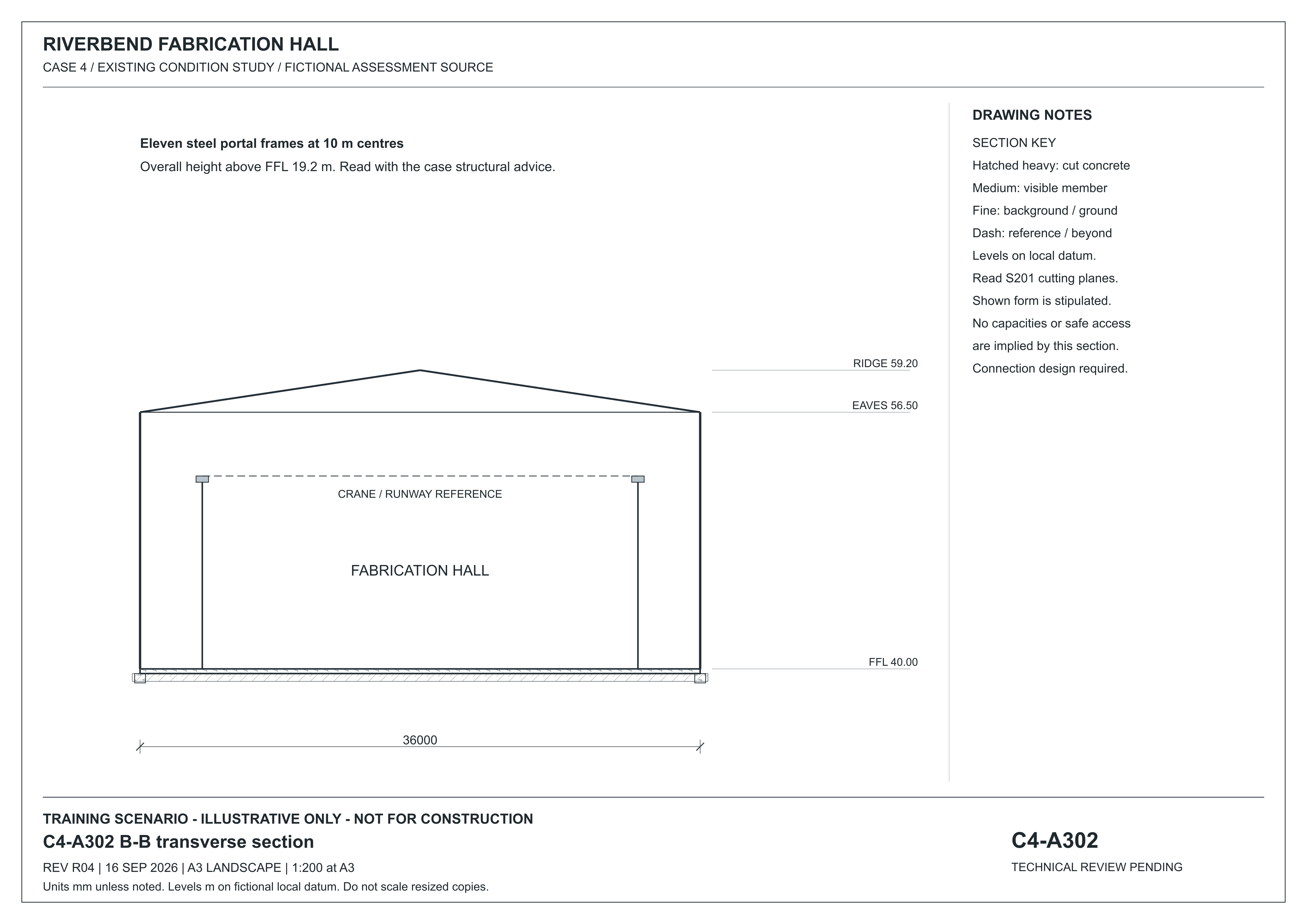
Riverbend's initial fictional records identify portal frames, purlins and girts, a crane runway and an independent office mezzanine. These names describe connected but distinguishable parts of the model. Use the plan and sections to locate them before discussing a member in isolation.
A runway can introduce actions through its supporting members and connections. An independent mezzanine should not be assumed to brace the main hall merely because both appear in one view. The initial drawings help locate the systems; their presence does not certify lifting capacity, temporary stability or a demolition sequence.
B-B transverse section
CONTROLLED FICTIONAL TRAINING RESOURCE Use with the nominated calculation model and records; an image is not engineering confirmation or permission to act.
 Open full-size illustration
C4-A302 R04 – B-B transverse section. B-B transverse section of Riverbend Fabrication Hall, identifying floor, eaves and ridge levels and the stated structural system. Local datum, not an engineering design. Reproduced in this guide at reduced size; use written dimensions, not a ruler on this page.
Use with the nominated calculation model and records; an image is not engineering confirmation or permission to act.
This visual is draft case-study teaching material. Reading it is not an inspection, a measurement or evidence of performance.
A roof is an assembly with restraint and weather functions
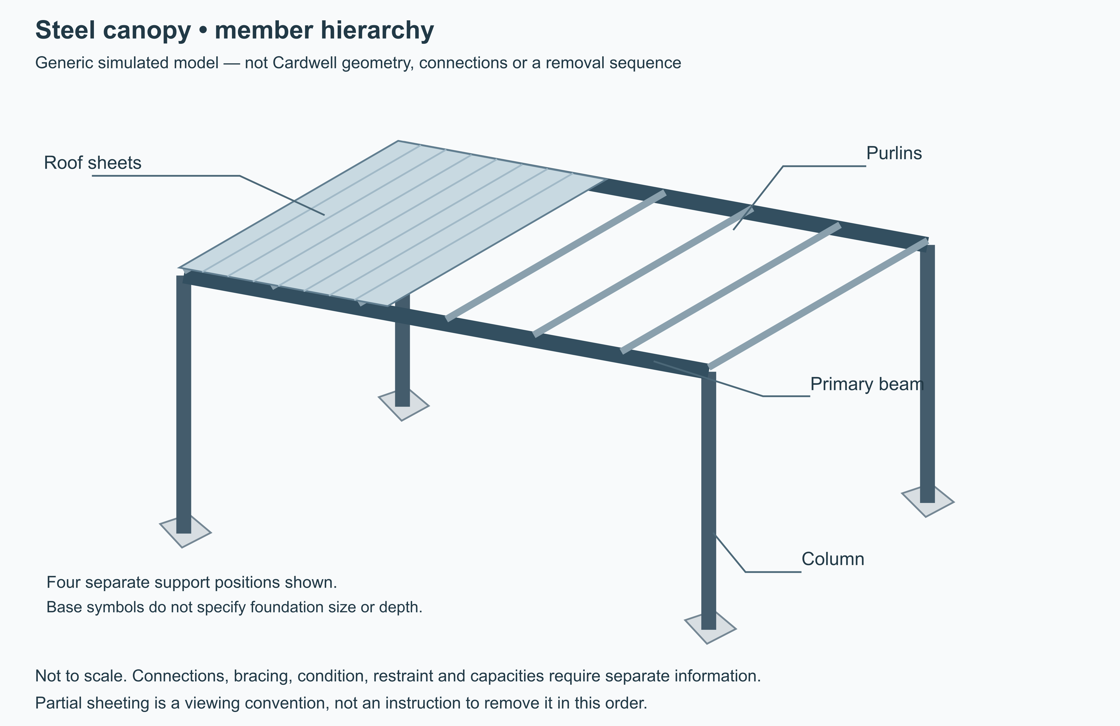
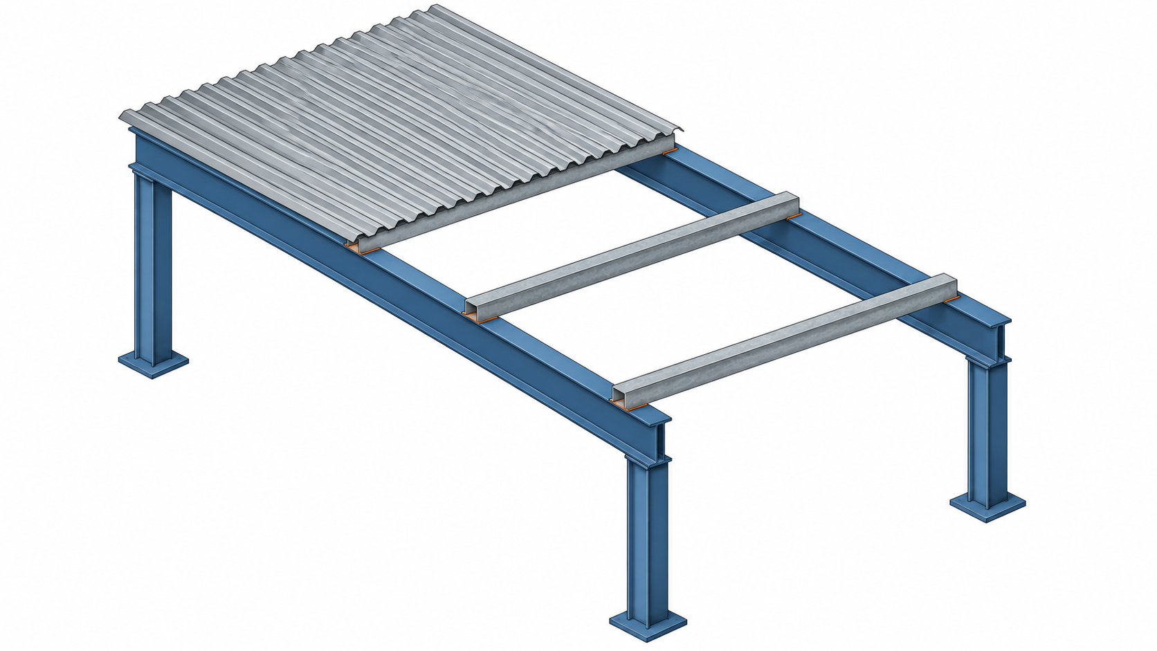
Roof systems may use rafters, trusses, portal frames, purlins, battens, sheeting and other components. Their names describe different roles. Purlins commonly support roof covering between principal frames or rafters. A truss uses connected members arranged so that forces are carried through its system. A portal frame relies on the intended behaviour of its frame and joints. Actual designs can differ from these general descriptions.
Roof bracing and connections can provide stability both to the roof and to the supporting walls or columns. Sheeting or other surfaces may contribute to diaphragm action or member restraint where the design relies on them. Removing covering can therefore do more than expose the interior to weather. It can change stiffness, restraint, wind loading and water entry.
Some systems include tension members or other components carrying stored force. A change at a connection can redistribute actions through the assembly. Roof trusses and long-span members must not be treated as independent short pieces simply because the work area below is small. Their force paths can extend beyond the visible bay.
Access is a separate question from structural appearance. Fragile roofing, rooflights, deteriorated surfaces and concealed openings can create fall hazards. The structural plan needs to account for the roof's load-bearing, restraint and weather functions at each stage. Hazardous-material information and access arrangements must also apply to the actual roof and proposed work.
Roof shape and roof framing are related, but they are not the same description. A hipped roof has sloping end surfaces as well as side surfaces. In conventional rafter construction, a hip rafter follows the sloping intersection. Shorter jack rafters meet it rather than extending to the main ridge.
A trussed hip end uses a designed assembly of members and connections. A truncated truss has a reduced or flattened upper profile to suit that assembly. A truncated girder truss can receive other roof members through specified connections. Similar outlines therefore do not prove identical member roles. Follow the actual layout and connection information before deciding what supports or restrains what.
These general distinctions are not a description of the actual Cronulla roof. They help explain why identifying a roof's shape is only the beginning of interpreting its structural system. LA-15 shows a separate generic steel roof hierarchy: covering, purlins, principal members and columns. It is not a removal sequence.
Members of a light steel canopy
LEARNING AID A teaching aid may illustrate a principle but does not establish a project fact, capacity, condition, authority approval or work release.
 Open full-size illustration
Generic light steel canopy with roof sheets, purlins, primary beams and columns
A teaching aid may illustrate a principle but does not establish a project fact, capacity, condition, authority approval or work release.
This visual is draft case-study teaching material. Reading it is not an inspection, a measurement or evidence of performance.
Roof sheets, purlins and primary members
LEARNING AID A generic learning aid explains a principle. It does not establish a project fact, hidden condition, capacity, approval or work release.
 Open full-size illustration
Follow the visible relationship from the corrugated roof sheet to the smaller crosswise purlins, then to the larger primary beams and vertical columns. The cutaway exposes the layers; it is not a removal sequence or a complete bracing/connection design.
A generic learning aid explains a principle. It does not establish a project fact, hidden condition, capacity, approval or work release.
This visual is draft case-study teaching material. Reading it is not an inspection, a measurement or evidence of performance.
Cladding has attachments, movement and material hazards
Cladding forms an external or internal covering and can include sheet materials, panels, masonry veneers, glazing and composite assemblies. It must transfer its own weight and applicable environmental actions through attachments into the supporting construction. A panel may also interact with seals, flashings, cavities and fire barriers. The visible face is only one part of the assembly.
Connections accommodate or restrain movement according to their design. Temperature change, frame movement and differential movement between materials can affect joints. Corrosion, failed fixings, cracked panels and altered supports can change the existing condition. A façade that appears undamaged from a distance may have concealed deterioration at its anchors or supporting edges.
Material identity is important for both the method and exposure controls. Older or unknown sheets and coatings require the appropriate hazardous-material evidence; appearance alone cannot rule asbestos or another hazardous constituent in or out. Composite panels can conceal different layers with different fire and handling characteristics. Glazing can create sharp fragments and may rely on frames, gaskets or specialised attachments that are not obvious from the surface.
A panel-recovery proposal therefore needs more than a count of panels. It needs the relevant material identity, connection information, condition, support and controlled handling arrangements. Separating enclosure components changes their own support and may also change the exposure or restraint of the structure behind them.
Retaining systems connect structure to soil and water
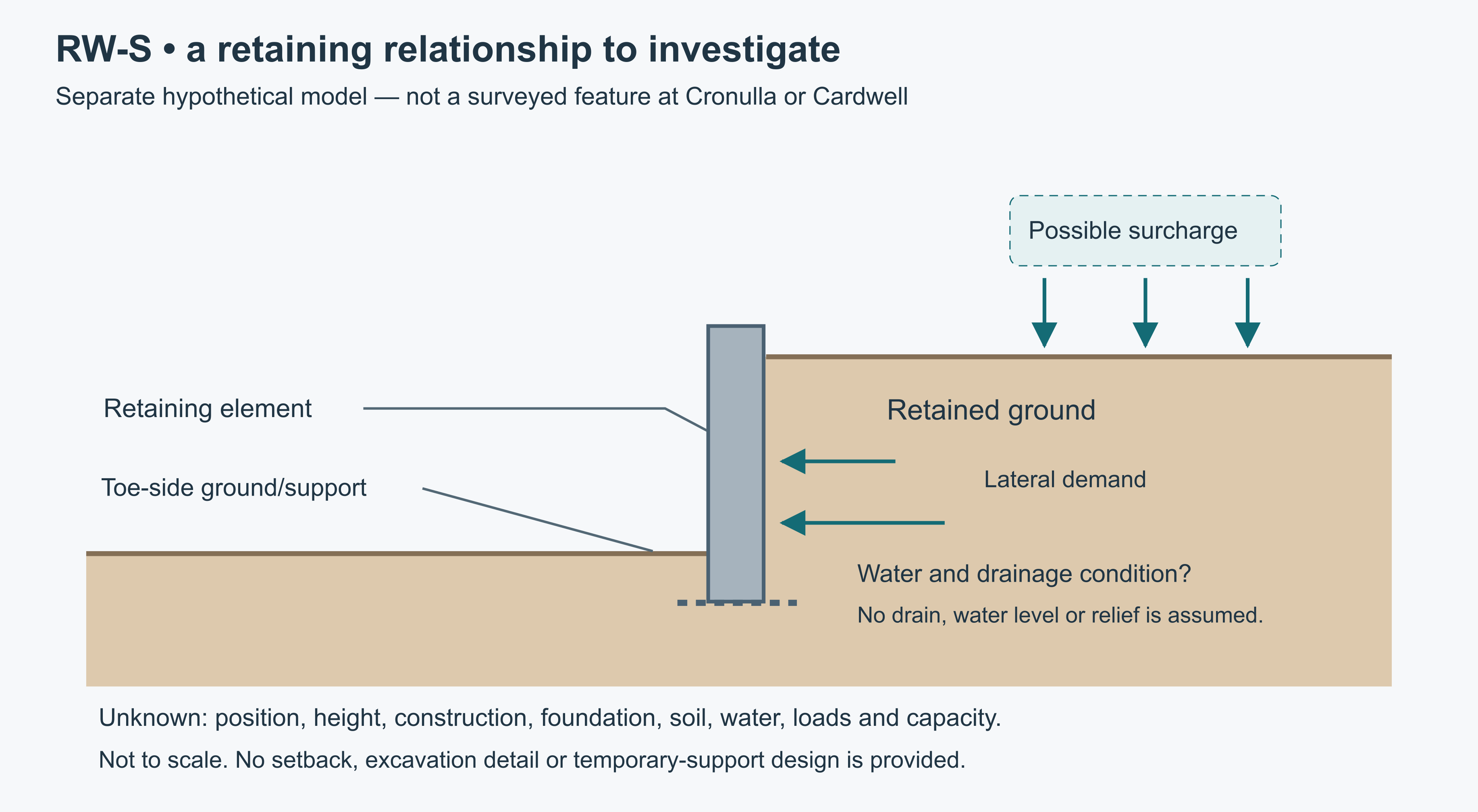
A retaining wall resists actions from material at different levels on its two sides. Its behaviour involves the wall, foundation, retained ground, drainage and any connected restraints or anchors. Water can add pressure and change ground conditions. Loads placed near the retained area can also influence the system. The visible wall is not an isolated object.
Basement walls can retain ground while also forming part of the building's structural and waterproofing systems. Floors may provide lateral restraint to those walls. Removing a floor can therefore change a retaining condition even if no soil has been excavated. Conversely, removing ground can affect foundations and support that appear to belong to an adjacent structure.
Retaining arrangements vary: gravity action, cantilever behaviour, embedded walls, anchors and propped systems are examples of different principles. These names do not tell a supervisor the capacity, support depth or safe modification for a particular site. Drawings, structural and geotechnical information and the actual condition must establish the relevant system.
For example, a basement slab may be proposed for removal while the external ground level remains unchanged. The slab may have a role in restraining the wall, separate from supporting ordinary floor loads. That possibility must be resolved in the structural plan, not dismissed because the slab is listed within the removal scope. Structural support and soil behaviour must be considered together.
The teaching aid LA-03 is labelled RW-S, a separate hypothetical retaining interface. It brings retained ground, a surcharge zone and a drainage question into one example. It is not a surveyed wall identified at Cronulla.
Use the example to explain why removing material on one side can change support, water behaviour or lateral demand. Keep that general reasoning separate from a claim that a particular photographed garden wall retains a particular depth of soil.
A separate retaining-ground example
LEARNING AID A teaching aid may illustrate a principle but does not establish a project fact, capacity, condition, authority approval or work release.
 Open full-size illustration
Separate hypothetical retaining interface with retained ground, surcharge zone and drainage question
A teaching aid may illustrate a principle but does not establish a project fact, capacity, condition, authority approval or work release.
This visual is draft case-study teaching material. Reading it is not an inspection, a measurement or evidence of performance.